


52
7/120 (P425AWIR), 9/110 (XP375AWIR), 10/105 (HP375AWIR), 14/85 (VHP300AWIR),
7/170 (P600WIR), 10/125 (HP450WIR), 14/115 (VHP400WIR)
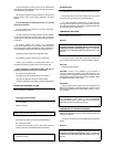
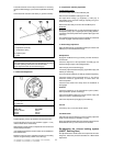
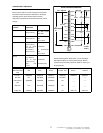
The brake actuators must not be pre–tensioned – if necessary
loosen the brake linkage [7] on the brake equalisation assembly
[8].
Check that brake actuators and cables [11] operate smoothly.
7 Brake linkage
8 Equalisation assembly
9 Compression spring
10 Equaliser plate
11 Cable
CAUTION
The compression spring [9] must only be lightly pre–tensioned
and when operating must never touch the axle tube.
Never adjust the brakes at the brake linkage [7].
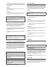
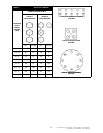
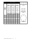
2. Brake Shoe Adjustment
12 Adjusting screw
13 Cable entry
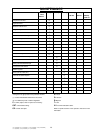
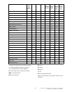
Width across flats of adjusting screw [12]
Brake size Key width
160x35 / 200x50 SW 17
250x40 SW 19
300x60 SW 22
Tighten adjusting screw [12] clockwise until the wheel locks.
Loosen adjusting screw [12] anti–clockwise (approx. ½ turn)
until the wheel can be moved freely.
Slight dragging noises that do not impede the free movement of
the wheel are permissible.
This adjustment procedure must be carried out as described on
both wheel brakes.
When the brake has been adjusted accurately the actuating
distance is approximately 5–8mm on the cable [11]
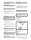
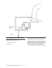
3: Compensator assembly adjustment
Variable Height models
Fit an M10 safety screw to the handbrake pivot.
Disconnect the handbrake cable [5] at one end.
Pre–adjust brake linkage [7] lengthways (a little play is
permissible) and re–insert the cable [5], adjusting it to give a
small amount of play.
Remove the M10 safety screw from the handbrake pivot.
All Models
Engage the handbrake lever [1] and check that the position of
the equaliser plate [10] is at right angles to the pulling direction.
If necessary correct the position of the equaliser plate [10] on the
cables [11].
The compression spring [9] must only be slightly pre–tensioned
and when engaged must not touch the axle tube.
4: Brake linkage adjustment
Adjust the brake linkage [7] lengthways without pre–tension and
without play in the transmission lever [4].
Readjustment
Engage the handbrake lever [1] forcefully a number of times to
set the brake.
Check the alignment of the equalisation assembly [8], this
should be at right angles to the pulling direction
Check the play in the brake linkage [7]
If necessary adjust the brake linkage [7] again without play and
without pre–tensioning
There must still be a little play in cable [5] (Variable Height Only)
Check the position of the hand brake lever [1]. The start of
resistance should be approximately 10–15mm above the
horizontal position.
Check that the wheels move freely when the handbrake is
disengaged.
Final test
Check the fastenings on the transmission system (cables,
brake equalisation system and linkage).
Check the handbrake cable [5] for a small amount of play and
adjust if necessary (Variable height only)
Check the compression spring [9] for pre–tensioning.
Test run
If necessary carry out 2–3 test brake actions.
Test brake action
Check the play in brake linkage [7] and if necessary adjust the
length of brake linkage [7] until there is no play.
Apply the handbrake while rolling the machine forward, travel of
the handbrake lever up to 2/3 of maximum is allowed.
Re–adjusting the overrun braking system
(KNOTT Running Gear)
Re–adjustment of the wheel brakes will compensate for brake
lining wear. Follow the procedure described in 2: Brake Shoe
Adjustment.