


04581922_ed4 EN-10
EN
Angle LSL - 0 degrees to Angle USL - 1
Angle USL - 1 to 3000 degrees
Trace Saved? - Yes or No
Cont. Output - Yes or No
Auto Print - Yes or No
Use the keys to scroll through the menu options
(displayed 1 per screen), and press ENTER to edit.
Menu options are edited by using the keys to
scroll through the options and then pressing ENTER.
To exit without changing, press ESCAPE.
To exit from any screen, press ESCAPE.
Cycle End Time
When the applied torque is removed, the wrench does not
immediately store the data. Instead it waits for the Cycle End Time
to count down to zero. This allows time for the operator to adjust
grip or ratchet the wrench. The Cycle End Time can be altered in
Angle Control Mode Setup.
Auto Print
The Auto Print feature allows the wrench to directly output
measurements to a printer or PC as they are taken. The
information appears as a single line of text showing the: date,
time, peak torque, torque compared to specications, peak angle,
angle compared to specications, and direction of fastening. The
formatting and spacing will be dierent based upon the number of
columns the operator has chosen under Printer Setup.
Continuous Output
Setting the Cont. Output to “Yes” in peak measurement modes
causes the wrench to output fastener torque on a second-by
second basis. This output can be sent to either a printer or a PC
using the supplied RS232 cable.
Trace saved?
Set “Trace saved?” to yes after a reading to store it in the Expert
Wrench memory. A trace includes information about the
conguration used to take the reading as well as a table of torque
and angle values. The traces can be uploaded to a PC using the PC
Comms software (sold separately). Up to 10 traces can be saved
in memory.
Canceling a Reading
To discard a reading, use the keys to highlight the
Cancel Icon and press ENTER. Press ENTER again to
conrm when prompted ‘Cancel reading?’
View Statistics
To view statistics about previous readings, use the keys to
highlight the Stats Icon and press ENTER. This brings
you to a table of calculated values for Mean X, R, σ, Cp, Cpk, Cm,
Cmk, CAM derived from the recorded torque and angle data.
Dierent pages of the table can be viewed by pressing the
keys.
Yield Control
Note: Yield Control should only be used on fasteners that have been
evaluated and qualied for yield tightening and high clamp loads.
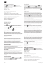
Yield Control provides maximum clamp load and reduced clamp
load scatter by tightening to the elastic limit of the bolt. Yield
Control mode alerts the operator to cease tightening as soon as
the yield point of the fastener has been reached (see below). The
Expert Torque Wrench calculates the yield point by monitoring the
torque/angle gradient as the fastener is tightened. It searches for
the peak gradient value and then lets the tightening continue until
the gradient falls to a predetermined fraction of the peak. As such,
two settings are of particular importance:
1. Threshold torque (generally 30-50% of the expected yield
torque). This is the point where the wrench begins to take gradi-
ent measurements.
2. Joint Type (Hard, Medium, or Soft). The joint type reects the
angle range over which the gradient is calculated. Hard should
be used for a snug-to-yield angle of < 30°, medium for 30°-120°,
and soft for > 120°.
To access the Yield Control mode scroll to Yield Control in the Main
Menu and press ENTER. The screen will immediately display
the word “WAIT” and both LEDs will turn red. During this time the
wrench is zeroing the angle sensor. Hold the wrench still until a
single LED is lit yellow to proceed.
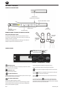
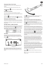
The default display shows torque units in large bold numbers in
the center of the screen, with angle data (as indicated by the angle
symbol on the left) above in a smaller font. The current torque units
are displayed alongside the torque data. The bottom left corner of
the screen says “YIELD” to indicate the current tightening mode.
The bottom right hand corner shows the current cycle number/
total number of samples.
Using the keys, two other displays can be accessed. One
shows the angle data in larger font with the torque data smaller in
the middle. The other shows both torque and angle in small font,
with current subgroup/total subgroups on the bottom.
Tighten the fastener at a moderate speed using a steady pull on
the wrench handle. As the wrench is pulled, the LEDs will change
color to represent various conditions. Both LEDs will turn solid
green when the lower torque limit is passed. Both LEDs will turn
solid red when either the upper torque or the upper angle limit
are passed. When the wrench nishes taking its measurement it
will beep and both LEDs will start ashing. As soon as the operator
hears the beep or sees the ashing light, he or she should stop
applying torque immediately to avoid over-tightening the fastener
beyond the yield point.
Note: As in the other modes, the wrench will also stop taking
measurements if torque is released and the cycle time expires. It will
also stop taking data if the angle is increasing too slowly (i.e. at a
speed of less than 4 degrees per second) and the Max Angle Time
expires.
When the measurement is complete the recorded values are
entered into the wrench memory. The most recent results will be
displayed on the screen until the next reading is taken. The LEDs
can also be used to give a quick analysis of the measurement.
Note: In Yield Mode, the LED ashes alternate to display two pieces of
information simultaneously.
The rst piece of information is a double Flash which indicates
whether the yield point was successfully detected. Both LEDs will
Flash green quickly if it was detected or yellow slowly if it was not.
The second piece of information is an alternate Flash sequence
which indicates whether the torque and angle values recorded at
the yield point were within the ranges specied by the operator.
The top LED represents the relative torque value. It will ash yellow
if the torque is below the specied range, green if it is within, and
red if it is above. In a similar fashion the lower LED will ash to
indicate whether the resultant angle was below, within, or above
the specied range. There are also arrows that appear to the right
of the torque and angle values. An upward arrow means that the
given value is above the specied range, and a downward value
means that it is below the range.
Yield Control Setup Menu:
Use the keys to highlight the Setup Icon and press
ENTER to access the Yield Setup Menu. This menu allows the
operator to change: