


M107
26
3
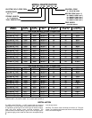
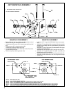
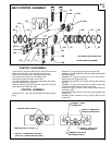
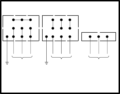
ELECTRICAL CONNECTION DIAGRAM
3 PHASE, 50 / 60 Hz
* RECOMMENDED OVERLOAD SETTING.
SUPPLY 220 V
SUPPLY 230 V
*(50 Hz 1.8 - 2.0 amp.)
*(60 Hz 1.6 - 2.0 amp.)
654
321
987
GROUND
LINE A
LINE B
LINE C
SUPPLY 440 V
SUPPLY 460 V
*(50 Hz .9 - 1.0 amp.)
*(60 Hz .8 - 1.0 amp.)
GROUND
LINE A
LINE B
LINE C
654
321
987
SUPPLY 550 V
SUPPLY 575 V
*(60 Hz X.X - X.X amp.)
123
LINE A
LINE B
LINE C
TO REVERSE ROTATION: INTERCHANGE ANY TWO LEADS.
WARNING: BE SURE THE ELECTRICAL POWER SUPPLY IS
OFF BEFORE MAKING ANY ELECTRICAL WIRING CONNEC-
TIONS.
WARNING: FAILURE TO PROPERLY GROUND THE MOTOR
MAY CAUSE SERIOUS INJURY TO PERSONNEL.
DO NOT BLOCK THE AIR FLOW TO OR FROM THE MOTOR
COOLING FAN. DO NOT DAMAGE THE MOTOR FAN COVER.
KEEP SMALL OBJECTS CLEAR OF THE OPENINGS IN THE
FAN COVER.
Connect the motor starter to the motor as shown in the wiring dia-
gram. The minimum wire size should be AWG No. 14, or equiva-
lent, (4107 circular mil) and conform to local / national regulations
governing the use of this type of electrical equipment.
Once the motor is connected, turn on the power supply. If the
spindle fails to rotate or rotates in the wrong direction, de–ener-
gize the motor starter immediately. Turn off the power supply and
recheck the wiring.
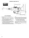
SET–UP PROCEDURE
WARNING: Keep clear of rotating end of unit with hands and/or
clothing.
• Shut off air supply to tool.
• Loosen screw (41), releasing cover (33).
• Determine the TOTAL STROKE LENGTH the drill must travel
to perform the drilling operation.
• Loosen cap screw (28) securing yoke assembly (27) to quill
(55) and position yoke assembly on quill approximately 5/8”
(16 mm) greater distance between control valve (39) and yoke
assembly than the distance of the Total Stroke Length.
• Tighten cap screw (28), securing yoke assembly (27) to quill
(55).
• Loosen nut (29), securing cap screw (30) and turn cap screw
(30) so the distance between the head of the cap screw (30)
and control valve (39) equals the total stroke length.
• Tighten nut (29), securing cap screw (30).
• Replace cover (33), securing with screw (41).
• Attach air supply to tool.
FEED RATE CONTROL VALVES
• Turn valve (103), marked ‘‘R” at side of control assembly (93),
approximately 1–1/2 turns counter–clockwise (open) from the
closed position.
• Turn the other valve (103), marked ‘‘F” at side of control as-
sembly (93), clockwise until closed (do not tighten too snugly).
• Start the unit and slowly turn valve (103) marked ‘‘F” counter–
clockwise (open) until the desired forward rate of feed is
reached.
• A final adjustment of the rate of return (retract) can be made
with the valve (103) marked ‘‘R”.
DISASSEMBLY/ASSEMBLY INSTRUCTIONS
• Disconnect air and electrical supply ‘‘BEFORE” performing
maintenance or service to tool.
• Never apply excessive pressure by a holding device which
may cause distortion of a part.
• Apply pressure evenly to parts which have a press fit.
• Apply even pressure to the bearing race that will be press
fitted to the mating part.
• Use correct tools and fixtures when servicing this tool.
• Don’t damage ‘‘O” rings when servicing this tool.
• Use only genuine ARO replacement parts for this tool. When
ordering, specify part number, description, tool model number
and serial number.
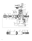
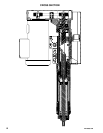
BELT AND PULLEY SECTION DISASSEMBLY
_ Remove four screws (1), releasing cover (2).
_ Loosen cap screw (13), loosening tensioner assembly.
_ Remove belt (3).
_ Remove cap screws (4) and washers (5), releasing pulleys (7
and 12) and keys (6).
_ To remove motor (11), remove four cap screws (9).
_ Remove cap screw (13), releasing tensioner assembly.
_ To disassemble, remove retaining ring (14), releasing spring
washer (15), bearings (16) and tension wheel (17).
BELT AND PULLEY SECTION ASSEMBLY
_ Apply thread adhesive (Loctite 242) to threads of tension
wheel pin (18) and assemble to bracket (19).
_ Assemble bearing (16), tension wheel (17) and bearing (16) to
tension wheel pin (18), securing with spring washer (15) and
retaining ring (14).
_ Assemble tensioner assembly to housing (10), securing with
cap screw (13). Do not tighten cap screw.
_ Assemble motor (11) to housing (10), securing with four cap
screws (9).
_ Assemble keys (6) and pulleys (7 and 12) to spindle (23) and
motor spindle.
_ Apply thread adhesive (Loctite 290) to threads of cap screws
(4) and assemble screws and washers (5) to spindles, secur-
ing pulleys. NOTE: Tighten screws (4) to 50 – 60 in. lbs.
_ Assemble belt (3) over pulleys (7 and 12) and inside belt ten-
sioner.
_ Hold tensioner assembly firmly against belt (3) and secure by
tightening cap screw (13).
_ Assemble cover (2) to housing, securing with four screws (1).
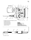
PULLEY SPINDLE SECTION DISASSEMBLY
_ Follow instructions for disassembly of BELT AND PULLEY
SECTION and remove belt (3) and pulley (12).
_ Remove four cap screws (20) and separate drive housing (10)
from frame assembly (35). NOTE: Housings will have to be
pulled apart approximately 11” (279 mm) to completely sepa-
rate pulley spindle (23) from frame assembly (35).
_ Using a spanner type wrench, unthread and remove lock
screw (25).
_ Pull spindle (23) and components from housing (10).
_ NOTE: Bearings (21) are press fit on spindle (23). Do not re-
move unless it should become necessary to replace, as Brin-
elling of the bearing races may occur, making replacement
necessary.