


4
DISASSEMBLY/ASSEMBLY INSTRUCTIONS
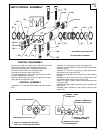
PULLEY SPINDLE SECTION ASSEMBLY
_ Assemble felt seal (24) to lock screw (25).
_ Assemble bearing (21) to ‘‘pulley” end of spindle (23), press-
ing on inner race of bearing.
_ Assemble spindle (23) and bearing into housing (10), press-
ing on outer race of bearing.
_ Assemble bearing spacer (22) and bearing (21) onto spindle,
pressing on inner race of bearing.
_ Assemble lock screw (25) to housing (10), securing spindle
and components.
_ Apply approximately 1/4 oz. (7 g) of ARO 33153 grease to in-
ternal splines of spindle (23) and assemble housing (10) and
components to frame assembly (35), securing with four cap
screws (20).
_ Refer to ‘‘BELT AND PULLEY SECTION” to complete the as-
sembly procedure.
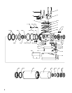
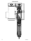
PISTON SECTION DISASSEMBLY
_ Loosen upper cap screw (28) on yoke assembly (27) to allow
for removal of quill (55).
_ Using a strap type wrench, unthread and remove outer sleeve
assembly (64) and components from the tool. NOTE: Remove
sleeve (64) with care. Pull sleeve straight away from the tool
so as not to bend the piston cylinder (63), damaging the inside
diameter.
_ Remove spindle nut (62) and locknut (68).
_ Remove spindle (58), bearing stop (60), bearings (59), spacer
(57) and bearing (56) from quill (55).
_ Remove quill (55) and piston cylinder (63) from sleeve. NOTE:
Handle the piston cylinder carefully to prevent damaging or
distorting the inside diameter.
_ Remove piston cylinder (63) from quill (55).
_ Remove seal (50) and unthread and remove plate nut (51), re-
leasing plate (52) and spring washer (53).
_ Do not remove wiper (26) from groove in frame assembly (35),
unless damage is evident. To remove wiper (26), refer to
‘‘Pulley Spindle Section” to separate drive housing (10) from
frame assembly (35).
_ Remove two cap screws (32), releasing stabilizer rod (31) and
yoke assembly (27) from tool. Wiper (26) can now be re-
moved.
PISTON SECTION ASSEMBLY
_ Grease wiper (26) with ARO 36460 lube and assemble to
groove in frame assembly (35). NOTE: Assemble wiper with
lips towards ‘‘chuck” end of tool.
_ Assemble yoke assembly (27) to stabilizer rod (31) and as-
semble stabilizer rod to frame assembly (35), securing with
two cap screws (32).
_ Refer to ‘‘Pulley Spindle Section” to assemble housing (10) to
frame assembly (35).
_ Grease wiper (67) with ARO 36460 lube and assemble to
groove in front bushing of outer sleeve assembly (64), with lips
of wiper facing towards sleeve (64).
_ Grease wipers (54) with ARO 36460 lube and assemble to
grooves in quill (55), with lips of wipers facing away from each
other.
_ Assemble spring washer (53) and plate (52) to quill (55), se-
curing with plate nut (51).
_ Assemble square seal (50) to quill (55).
_ Assemble bearing (56) to spindle (58), pressing on inner race
of bearing.
_ Assemble spindle (58) and spacer (57) into quill (55).
_ Pack bearings (59) with ARO 33153 grease and assemble
onto spindle (58) and into quill (55). NOTE: Assemble bear-
ings with open faces together (shielded sides facing out).
_ Assemble wiper (61) to groove in bearing stop (60), assem-
bling with lip of wiper toward the ‘‘chuck” end of the tool.
_ Assemble bearing stop (60) into quill (55).
_ Assemble spindle nut (62) to spindle and tighten securely.
_ Lubricate i.d. of piston cylinder (63) and o.d. of quill (55) with
ARO 36460 lube and assemble into outer sleeve assembly
(64). Handle piston cylinder with care so as not to damage or
distort the i.d.
_ Assemble locknut (68) to quill (55) and tighten securely.
_ Grease ‘‘O” rings (48 and 49) with ARO 36460 lube and as-
semble to grooves in frame assembly (35).
_ Assemble outer sleeve assembly (64) and components to
frame assembly (35), assembling quill (55) thru yoke assem-
bly (27). Tighten outer sleeve securely. NOTE: Use caution
when inserting quill (55) thru frame assembly so as not to
damage wiper (26).
_ Tighten upper cap screw (28), securing yoke assembly.
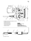
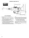
VALVE HOUSING SECTION DISASSEMBLY
_ Control valves (37 and 39), manifold assembly (77) and con-
trol assembly (93) can be serviced without disrupting any oth-
er section of the tool.
_ Remove set screws (36 and 40), releasing control valves (37
and 39).
_ To service bushing assembly (45), pin (44), stem (43) or
spring (42), remove outer sleeve assembly (64) and compo-
nents as described in ‘‘PISTON SECTION”.
_ Remove three cap screws (47), releasing piston stop (46).
_ Remove bushing assembly (45), pin (44), stem (43) and
spring (42).
_ See pages 8 and 9 for disassembly and assembly of manifold
assembly (77) and control assembly (93).
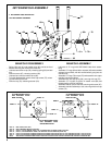
VALVE HOUSING SECTION ASSEMBLY
_ Lubricate all ‘‘O” rings with ARO 36460 lube when assem-
bling.
_ Assemble control valves (37 and 39) to frame assembly (35),
securing with set screws (36 and 40). Set screws must be air
tight.
_ Assemble spring (42) to stem (43) and assemble into frame
assembly.
_ Assemble pin (44) into bushing assembly (45) and assemble
into frame assembly.
_ Assemble piston stop (46) to frame assembly (tangs on mag-
net facing away from frame) and secure with three cap screws
(47). TIGHTEN TO 45–50 IN/LBS.
_ Assemble outer sleeve assembly (64) and components to tool
as described in ‘‘PISTON SECTION”.