


20
DISASSEMBLING THE IR90VR SERIES PAVING BREAKERS
GENERAL INSTRUCTIONS
• Do not repair the tool at the work site. Always take the
tool to a repair shop. Never drag the tool on the ground.
The air port and other openings will become clogged
with dirt and debris.
• Clean the breaker outer surface.
• Do not disassemble the breaker any further than
necessary to replace or repair damaged or worn parts.
• Whenever grasping a breaker or a part in a vice, always
use leather or copper-covered vice jaws to protect the
surface of the part and help prevent distortion. Take
extra care with threaded parts and housings.
• Do not remove any part that is a press fit in or on a sub-
assembly unless the removal of the part is necessary for
repairs or replacement.
• Do not disassemble the breaker unless a complete set of
O-rings is available for replacement.
DISASSEMBLY OF THE FRONT HEAD
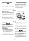
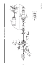
Remove nut (25) and fronthead pinch bolt (24) from the
fronthead (3). Lightly tap the fronthead (using a hide mallet
if necessary) from the cylinder (1).
Press or drift out the two fronthead spring pins (22, 23) and
remove the latch (6).
The plunger (20) and the plunger spring (21) can be removed
from the fronthead.
HANDLE DISASSEMBLY
Using a hide mallet tap loose and remove the muffler (29)
from the cylinder.
Firmly grip the cylinder upright in a vice with leather or cop-
per covered jaws.
Loosen the four-handle nuts (27), unscrew and remove the
four-handle screws (26).
Lift the handle assembly (5) from the cylinder (1) (tap with a
hide mallet if necessary).
Press or tap out the handle pivot pin (12), remove both han-
dle levers (8 and 9) from the handle body (5) together with
the trigger (7). Tap out the sleeve (13) to detach the handle
levers from each other. Remove the handle springs (11)
from the handle body (5). If it is necessary to remove the
handle lever stop (14), use a punch of a suitable size Ø.60-
.75 in. (Ø15-19 mm) and drift the stop out from the
cylinder side.
Note: The Stop will be destroyed if removed.
It is possible to remove the trigger pin (15) at this stage if
required.
Unscrew the inlet bushing (18), and remove trigger spring
(17) the trigger ball (16) and throttle pin (15).
Remove the handle grips (10). It may prove easier to cut off
the old handle grips if they are to be replaced.
CYLINDER DISASSEMBLY
Remove the spacing washer (30) and valve plate (31). Slide
valve ring (34) from cylinder (1).
Remove sealing ring (28).
Release the cylinder from the vice, invert and allow the pis-
ton (4) to slide out and be caught.
The nozzle (2) is pressed in the cylinder and retained with
Loctite 601 – do not disassemble unless replacement is
necessary.