


21
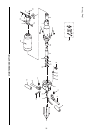
ASSEMBLY OF THE IR90VR SERIES PAVING BREAKERS
GENERAL INSTRUCTIONS
• Do not repair the tool at the work site. Always take the
tool to a repair shop. Never drag the tool on the ground.
The air port and other openings will become clogged
with dirt and debris.
• Before assembly of the breaker, clean all parts thor-
oughly and lubricate surfaces with a thin film of recom-
mended oil (see Lubrication).
• Apply a film of O-ring lubricant to all O-rings before
final assembly.
• It is recommended that the assembling of the nozzle (2)
should be carried out by the manufacturer or authorised
distributor.
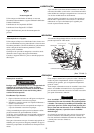
• The existence of a piston air cushion should be deter-
mined. Hold the cylinder vertically and allow the piston
to drop down the bore small diameter first. An air cush-
ion is present if the piston “bounces” at the bottom of
the cylinder and no metal to metal contact noise can be
heard. If a cushion is not present contact your authorised
Ingersoll-Rand repair center for advice.
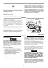
CYLINDER ASSEMBLY
Grip the cylinder (1) vertically in a vice protected with
leather or copper covered vice jaws.
Lubricate and insert the piston (4) small end first into the
bore. Check for cushion.
Lubricate and slide the valve ring (34) onto the cylinder (1)
and replace valve cover (31).
Position the valve spacer (30) on top of the valve cover (31).
Replace the sealing ring (28).
HANDLE ASSEMBLY
If the handle stop (14) was removed during disassembly it
should be replaced with a new part as the retaining feature
is severed on removal. Locate the stop in the hole in the han-
dle and tap sharply into place using a soft drift and hammer.
If the hand grip rubbers (10) have been removed these
should now be replaced. Lubricate the inside of the rubber
with soapy water and slide the new rubber into position.
Assemble left and right hand, hand grips (8 and 9), trigger
(7) together with sleeve (13), lubricate around the pivot area
and position the sub assembly along the slot in handle body
(5).
Note: It is usual to position the trigger lever on the same
side as the air inlet of the handle body.
Locate the handle springs (11) between hand grips and han-
dle body and fix the assembly in place by drifting or pressing
in handle pivot pin (12).
Lubricate the trigger pin (15), trigger ball (16) and replace
in the air inlet connection of the handle body.
Note: The trigger pin has a reduced diameter which is
placed next to the trigger ball.
Locate the trigger spring (17) on top of the trigger ball.
Apply thread retainer (loctite 243, or similar) on the thread
of the inlet bushing (18) and tighten to 147 lb. ft (200 Nm)
torque. Check that the handles and trigger move freely.
MAIN ASSEMBLY
Lightly grip the cylinder assembly vertically in a vice and
position the handle assembly in place.
Note: It is usual to orientate the trigger lever and air inlet
180 degrees from the fronthead bolt groove in the
cylinder.
Replace the four handle screws (26) use new handle nuts
(27) and tighten down evenly to a torque of 66.4 lb. ft
(90 Nm) torque.
Remove the cylinder and handle assembly from the vice.
Replace the muffler (29) on the assembly by tapping the
muffler fully home using a hide mallet.
FRONT HEAD ASSEMBLY
Apply a coating of grease then replace spring (21) and
plunger (20) in position in fronthead (3).
Position the latch (6) in its slot and secure in place by drift-
ing or pressing in outer spring pin (23). Position then press
or drift home inner spring pin (22).
Replace fronthead assembly onto cylinder and aligning
pinch bolt hole with the cylinder groove.
Replace pinch bolt (24) and nut (25) and tighten a torque of
147 lb. ft (200 Nm) torque.
ASSEMBLY CHECKS
Following service, the breaker should be checked for correct
operation prior to being released back to the job site.
Fit the correct size accessory into the breaker and connect to
an airline. Using air at low pressure 30 psi (2 bar), check
that the breaker is free from air leaks around the inlet con-
nection and that the breaker does not automatically start to
operate without the trigger being depressed.
Increase the air pressure to 90 psi (6 bar) and run the tool in
short bursts to check the tool operates correctly and stops
and starts cleanly without hesitation.
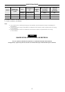
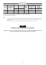
Breaker operating frequency should be 960 blows per minute
and air consumption 60 CFM (1.85m
3
/min) at 90 psi (6 bar)
air pressure.