


IRN37 - 160K - CC & IRN50 - 200H -CC & IRN75 - 160K - 2S & IRN100 - 200H - 2S & IRN 250 - 300H - 2S
http://air.irco.com
38
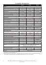
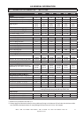
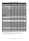
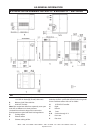
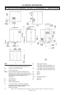
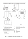
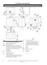
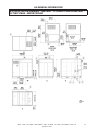
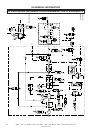
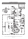
8.0 GENERAL INFORMATION
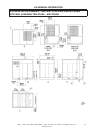
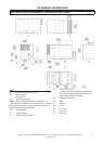
KEY
A 2” NPT Air discharge (Female) 60Hz units
(N100H−N150H)
2” BSP Air discharge (Female) 50Hz units
(N75K−N110K)
2 1/2” NPT Air discharge (Female) 60Hz units
(N200H)
2 1/2” BSP Air discharge (Female) 50Hz units
(N132K and N160K units)
B Electrical inlet −
Ø75mm (3”)
Ø64mm 575V (Option)
C 0.38“ NPT (Female)
Note: Pipe condensate drain lines separately to an open
drain due to differences in drain pressures. Use drain
lines at least as large as the connection. Read operations
manual and check local regulations
D Cooling airflow
E Exhaust airflow
F Cabinet cooling airflow
G 4 x Ø 13.0mm (0,5”)
Compressor should be bolted to the floor with
four M10 (0.38”) bolts using holes shown. Seal
base to floor with cork or rubber.
H INTELLISYS Controller
J 1.5” NPT Water inlet (Female) 60Hz units
1.5” BSP Water inlet (Female) 50Hz units
K 1.5” NPT Water outlet (Female) 60Hz units
1.5” BSP Water outlet (Female) 50Hz units
U Right
V Bottom
W Front
X−X Section through X−X
Y Rear view
Z Plan view