


IRN37 - 160K - CC & IRN50 - 200H & IRN75 - 160K - 2S & IRN - 100 - 200H - 2S & IRN 250 - 300H - 2S
http://air.irco.com
85
10.0 MAINTENANCE
Separator element change procedure for N250/
300H−2S
Disconnect the scavenge tube at the airend.
Loosen the fitting that holds the scavenge tube into
the tank and withdraw the tube assembly
Disconnect the piping from the tank cover. Tag the
lines if required.
Use a suitable wrench and remove the bolts that
hold the tank cover in position. Remove cover by
lifting up and away.
Carefully lift the separator element up and out of the
tank. Discard the faulty element.
Clean the gasket surface on both the tank and its
cover. Exercise care to prevent pieces of the old
gasket from falling down into the tank.
Check the tank to be absolutely certain that no
foreign objects such as rags or tools have been
allowed to fall into the tank. Install replacement
element down into the tank after checking the new
element gaskets for possible damage. Center the
element up within the tank.
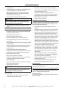
Place the tank cover in its correct position and
install bolts. Tighten the bolts in a cross−pattern to
prevent over−tightening one side of the cover. An
improperly tightened cover will likely result in a leak.
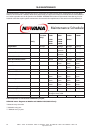
Tank cover bolt torque values
250−300 HP
3/4−10 UNC
210ft−lb. (285 n−M)
Inspect tank scavenge screen and orifice. Clean if
necessary following instructions in Section 4.7.
Install scavenge tube down into the tank until the
tube just touches the separator element and then
raise it 1/8inch (3.2 mm). Tighten fittings.
Install the regulation lines in their original position.
Start unit, check for leaks, place in service.
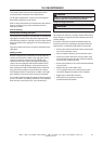
RECOMMENDED BOLT TIGHTENING
CROSS PATTERN
250 − 300 HP
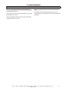
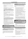
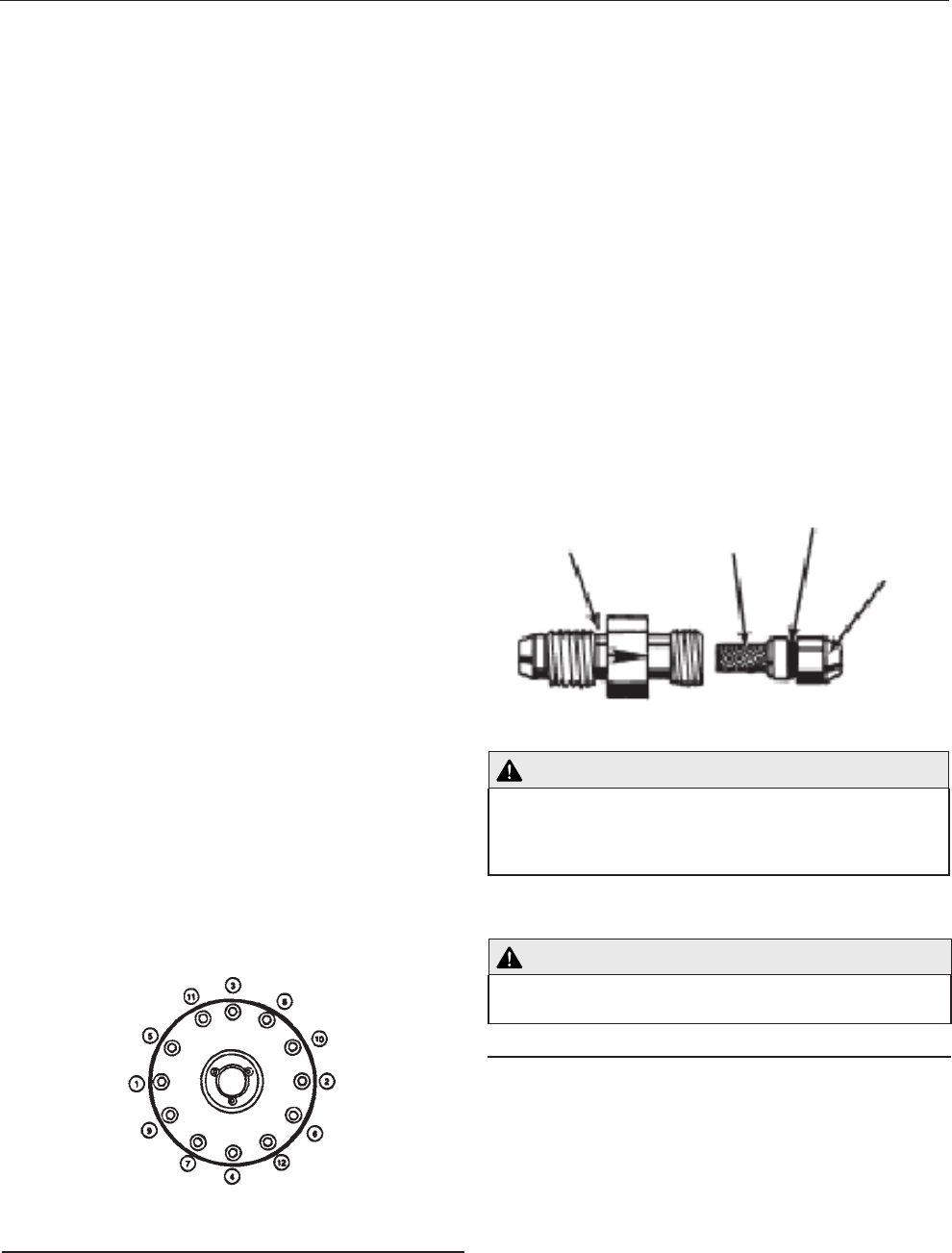
Scavenge screen clean/check procedure
The screen/orifice assemblies are similar in appearance to
a straight tubing connector and will be located between
two pieces of 1/4 inch O.D. scavenge line tubing.
•
•
•
•
•
•
•
•
•
•
•
•
•
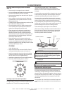
The main body is made from 1/2 inch hexagon
shaped steel and the diameter of the orifice and a
direction−of−flow arrow is stamped in flat areas of the
hexagon.
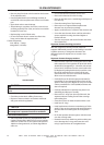
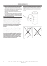
A removeable screen and orifice is located in the exit end
of the assembly. (see figure) and will require clearing as
outlined in the Maintenance Schedule Section 10.2.
To remove the screen/orifice, disconnect the scavenge
line tubing from each end. Hold the center section firmly
and use a pair of pliers to gently grasp the exit end of
the assembly that seals against the scavenge line tubing.
Pull the end out of the center section while using care to
prevent damage to the screen or sealing surfaces.
Clean and inspect all parts prior to reinstallation.
When the assembly is installed, confirm the direction of
flow to be correct. Observe the small arrow stamped in
the center section and ensure the direction flow to be
from the separator tank to the airend.
ORIFICE
SCREW HOUSING
SCREEN
O−RING
SEPARATOR TANK SCAVENGE SCREEN/ORIFICE
WARNING
Unscrew the jacking bolt sufficiently to ensure that
the cover can be fully tightened down without im-
parting any stress onto the jacking points. Tighten
down the cover setscrews.
Start the compressor and check for leaks and
coolant level.
CAUTION
Do not use any form of sealant on either the separa-
tor tank or the separator tank cover faces.
Separator tank / Pressure system
At 2000 hour intervals, inspect the external surfaces of
the airend and separator tank, including all fittings, for
visible signs of impact damage, excessive corrosion and
abrasions. When changing the separator element inspect
the internal components and surfaces. Any suspect parts
should be replaced before the compressor is put back
into service.
The separator tank should also be tested and inspected
in accordance with any national or local codes that may
exist.
•