


IRN37 - 160K - CC & IRN50 - 200H & IRN75 - 160K - 2S & IRN - 100 - 200H - 2S & IRN 250 - 300H - 2S
http://air.irco.com
43
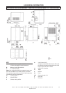
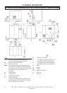
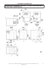
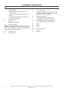
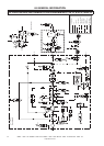
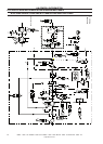
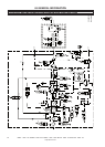
8.0 GENERAL INFORMATION
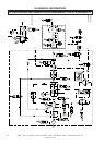
KEY
1 Air discharge
2 Compressor
3 Air filter
4 Vacuum switch 1VAC
5 Cooler, air
6 Cooler, coolant
7 Condensate discharge
8 Coolant filter
9 Pressure switch, coolant filter 1DPS
10 Drain valve, coolant
11 Temperature switch 1ATS
12 Air inlet check valve
13 Timed solenoid condensate drain.
(single stage)
14 Minimum pressure check valve
15 Moisture separator
16 Pressure transducer 4APT
17 Pressure relief valve
18 Scavenge filter / orifice / check
19 Separator tank (primary/secondary)
20 Oil temperature control valve
21 Temperature transducer 2ATT
22 3SV blowdown solenoid valve
23 Drive motor
24 Blower motor
25 Cooling air blower
26 Cooling water inlet (W.C. only)
27 Cooling water outlet (W.C. only)
28 Pressure transducer 3APT
29 Pressure transducer 6APT
30 Dryer (customer supply equipment)
31 Line filters (customer equipment)
32 Receivers (customer equipment)
33 Dryer AUX warning
34 Line filter AUX warning
35 Receiver trap AUX warning
36 Remote pressure transducer 9APT (optional)
37 Water stop valve 4SV
38 Typical customer downstream air treatment
39 Anti − condensation valve 11SV
40 Cooling air exhaust box
41 Package discharge temperature transducer 4ATT
42 Injected coolant temperature sensor
43 Seal scavenge air supply
44 Seal scavenge line
45 Air intake temperature sensor. 1ATT
46 Electronic drain trap. Alternative to item 13.
(Standard equipment on 2 stage. Optional on
single stage).
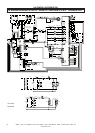
45 Interstage pressure relief valve. (2 stage.)
46 Interstage pressure transducer. (2 stage)
49 Air/Coolant separator element
Air/coolant
Air
Coolant
Condensate
Cooling water (W.C. only)
Compressor enclosure
Sensor connection
Equipment downstream of
compressor