


11
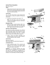
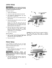
Jointer-Planer Assembly
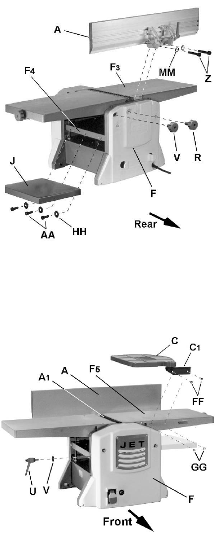
Referring to Figure 7:
Fence
1. Attach jointer fence (A) to back of jointer outfeed
table (F
3
) with two each socket head cap screws
(Z) and lock washers (MM). Tighten screws with
5mm hex wrench (provided).
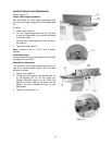
Lock Knobs
The JJP-10BT Jointer-Planer comes equipped with
two lock knobs to secure the position of the jointer
infeed table.
2. Install jointer infeed table lock knobs (V, R).
Note: The shaft length of each lock knob (refer
to Figure 3) are different. Be sure to install each
in the correct location.
Extension Table
3. Attach the planer outfeed extension table (J) to
the main planer table (F
4
) with three each
socket head cap screws (AA) and flat washers
(HH). Tighten screws with 5mm hex wrench.
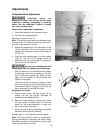
Extension Table Adjustment
Two setscrews located underneath the extension
table (J) are used to adjust the height position of the
outer (protruding) edge, which must be slightly
higher than the main planer table (F
4
) in order to
minimize snipe (see Avoiding Snipe on page 21).
4. Using a 4mm hex wrench (provided), turn
setscrews slightly clockwise to raise the table or
counterclockwise to lower the table.
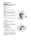
Lock Handle
Referring to Figure 8:
Attach planer table lock handle (U) and flat washer (T).
Cutterhead Guard
5. Install cutterhead guard (C) by securing the
bracket (C
1
) to the side of the jointer infeed
table (F
5
) with two each pan head machine
screws (FF) and hex nuts (GG).
Important: It is extremely important that spring
action causes the cutterguard (C) to retract against
the fence (A), concealing the cutterhead (A
1
). If
spring return tension is not enough, adjust the spring
located on the cutterhead pivot shaft accordingly.
Figure 7
Figure 8