


12
Jointer Setup
Disconnect machine from power
source before making any adjustments. Failure
to comply may cause serious injury.
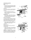
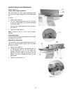
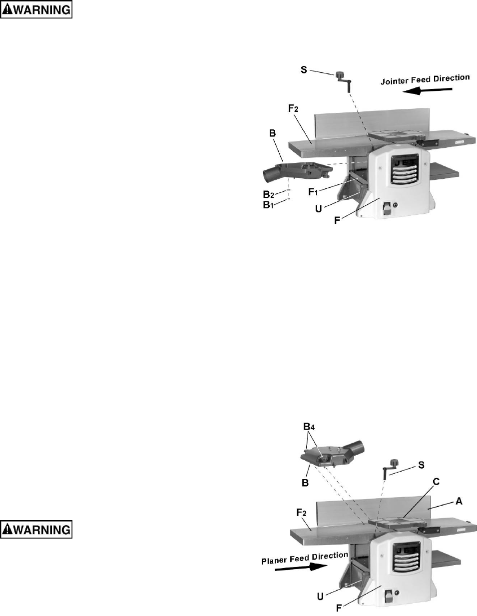
Referring to Figure 9:
1. Loosen lock handle (U).
2. Install planer table height adjustment handle (S).
3. Turn handle (S) counterclockwise and lower
planer table (F
1
) all the way.
4. Remove hex nut (B
1
) and flat washer (B
2
) from
dust chute (B).
5. Orient the dust chute (B) as shown and install
into the infeed opening.
Position the chute (B) such that the two
positioning keys and one threaded positioning
screw underneath the chute meshes with three
positioning holes on the table (F
1
).
6. Raise the table (turn handle S clockwise) until
the dust chute (B) is held firmly in place
between the planer infeed table (F
1
) and jointer
outfeet table (F
2
). Do not overtighten.
7. Tighten lock handle (U).
Step 8 is optional.
8. Further secure the dust chute by reinstalling the
hex nut (B
1
) and flat washer (B
2
) from
underneath the planer infeed table (F
1
).
9. Remove handle (S).
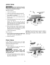
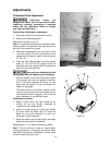
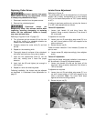
Planer Setup
If the machine is currently set up for jointer
operation, remove the dust chute (B, Fig. 9). Refer
to the Jointer Setup section above.
Referring to Figure 10:
1. Swing cutterguard (C) away from fence (A),
which will expose the cutterhead.
Cutterhead knives are
dangerously sharp. Use extreme caution when
working around them. Failure to comply may
cause serious injury.
2. Orient the dust chute (B) as shown. Install onto
the jointer outfeed table (F
2
) and secure by
tightening lock knobs (B
4
).
Figure 9
Important: Dust chute (B) must be properly installed in
both Jointer setup and Planer setup. If improper
installation fails to activate a micro-switch, the machine
will not start.
Figure 10