


11
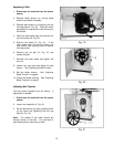
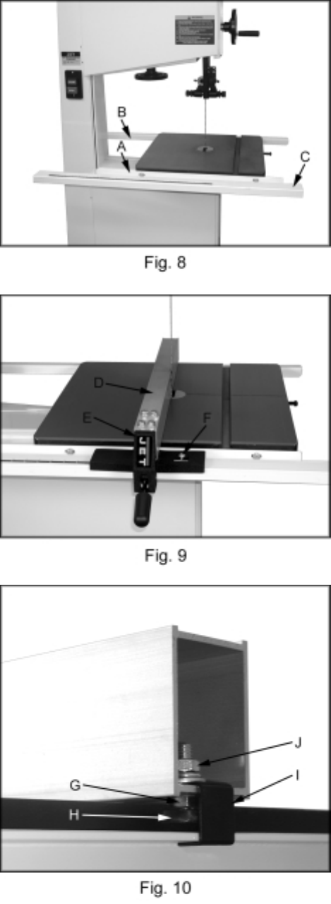
Rail Assembly (optional accessory)
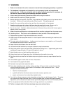
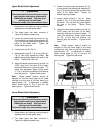
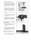
1. Attach the front rail (A, Fig. 8) to the cast
iron table with two 1/4” x 5/8” hex cap bolts,
two 1/4” lock washers, and two 1/4” flat
washers. Bolts should be in approximately
the center of the slot. Hand tighten only at
this time.
2. Attach the rear rail (B, Fig. 8) to the table
with two 1/4” x 5/8” hex cap bolts, two 1/4”
lock washers, and two 1/4” flat washers.
Bolts should be in approximately the center
of the slot. Hand tighten only at this time.
3. Push the front, and rear rails up as far as
they will go.
4. Tighten the four hex cap bolts holding the
front, and rear rails to the table. Do not
over tighten the bolts.
5. Attach the guide tube (C, Fig. 8) to the front
rail with five 1/4” x 5/8” hex cap bolts, five
1/4” lock washers, and five 1/4” flat washers.
Bolts should be in approximately the center
of the slot.
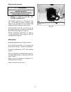
Fence Assembly and Adjustment
(optional accessory)
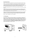
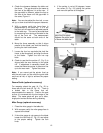
1. Attach the fence (D, Fig. 9) to the fence
body (E, Fig. 9) with four 5/16” x 3/4” hex
cap bolts, four 5/16” lock washers, and four
5/16” flat washers.
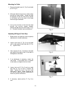
2. Thread a hex nut (G, Fig. 10) onto the pad’s
threaded stud (H, Fig. 10) and insert through
the fence and rear hook (I, Fig. 10).
Secure in place using a hex nut, lock washer
and flat washer (J, Fig. 10).
Note: The hook should be adjusted so that it
overlaps the rear rail by approximately 1/8”.
3. Place fence assembly onto the guide tube.
The rear hook should engage the rear rail.