


9
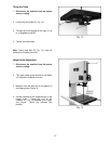
Upper Blade Guide Adjustment
WARNING
Disconnect machine from the power source,
unplug before making any adjustments!
Blade teeth are sharp! Use care when
working near the saw blade.
Failure to comply may cause serious injury!
1. Blade tension and tracking must be properly
adjusted prior to blade guide setup.
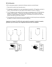
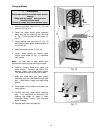
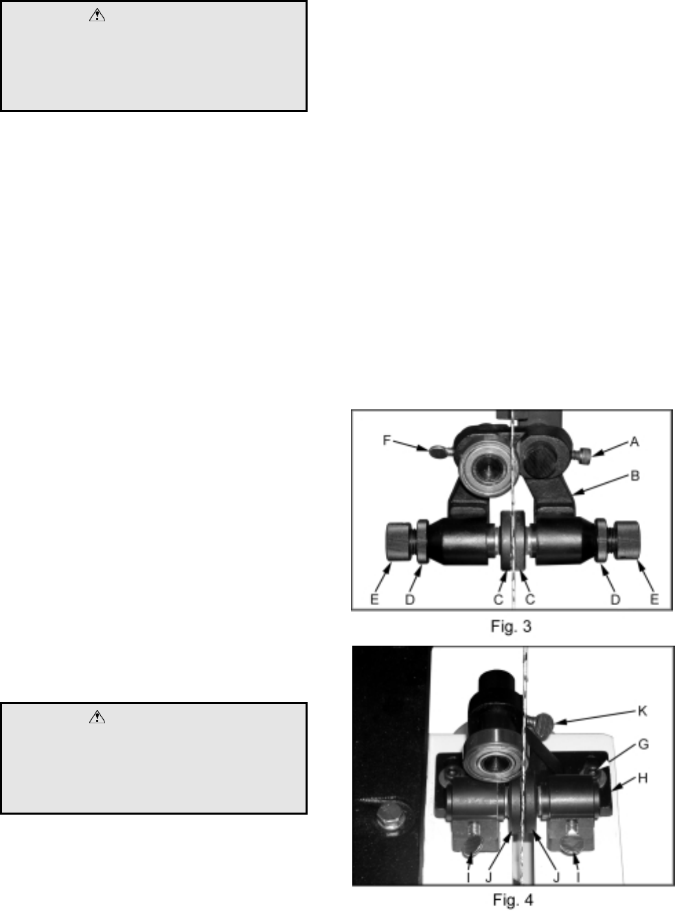
2. The blade guard has been removed in
Figure 3 for photo purposes only.
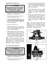
3. Loosen the socket head cap screw (A, Fig.
3) and position the blade guide assembly (B,
Fig. 3) so that the guides rest just behind the
gullet of the blade teeth. Tighten the
socket head cap screw.
4. Loosen lock nuts (D, Fig. 3).
5. Adjust guide knobs (E, Fig. 3) so guides (C,
Fig. 3) rest lightly against the blade. Do
not force the guides against the side of the
blade. Tighten both lock nuts.
6. Adjust the blade support bearing so that it is
0.003” away from the back of the blade,
about the thickness of a piece of paper. To
make this adjustment loosen thumb screw
(F, Fig. 3) and slide the bearing and bearing
post into position. Tighten thumb screw.
Note: Blade support bearing should be
adjusted so that the back edge of the blade
overlaps the front face of the ball bearing by
approximately 1/8”. If adjustment is needed,
loosen thumb screw (F, Fig. 3) and turn the
bearing shaft. Tighten thumb screw.
Lower Blade Guide Adjustment
WARNING
Disconnect machine from the power source,
unplug before making any adjustments!
Blade teeth are sharp! Use care when
working near the saw blade.
Failure to comply may cause serious injury!
1. Blade tension and tracking must be properly
adjusted prior to blade guide setup.
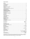
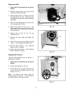
2. The blade guard has been removed in
Figure 4 for photo purposes only.
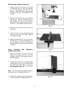
3. Loosen the socket head cap screws (G, Fig.
4) and position the blade guide assembly (H,
Fig. 4) so that the guides rest just behind the
gullet of the blade teeth. Tighten the
socket head cap screws.
4. Loosen thumb screws (I, Fig. 4). Adjust
guides (J, Fig. 4) so they rest lightly against
the blade. Do not force the guide against
the side of the blade. Tighten thumb
screws.
5. Adjust the blade support bearing so that it is
0.003” away from the back of the blade,
about the thickness of a piece of paper. To
make this adjustment loosen thumb screw
(K, Fig. 4) and slide the bearing, and
bearing post into position. Tighten thumb
screw.
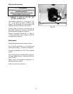
Note: Blade support bearing should be
adjusted so that the back edge of the blade
overlaps the front face of the ball bearing by
approximately 1/8”. If adjustment is needed
loosen thumb screw (K, Fig. 4) and turn the
bearing shaft. Tighten thumb screw.