


11
Alternatively, the lathe may be “hard-wired” to
the power source. If you are hard-wiring the
lathe to a panel, make sure a disconnect is
available for the operator. During hard-wiring
of the Lathe, make sure the fuses have been
removed or the breakers have been tripped in
the circuit to which the Lathe will be
connected. Place a warning placard on the
fuse holder or circuit breaker to prevent it
being turned on while the machine is being
wired.
7.3 Extension cords
The use of extension cords is discouraged; try to
position equipment within reach of the power
source. If an extension cord becomes necessary,
be sure it is heavy enough to carry the current your
product will draw. An undersized cord will cause a
drop in line voltage resulting in loss of power and
overheating.
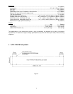
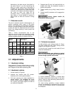
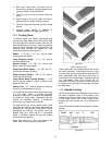
Table 1 shows recommended size to use
depending on cord length and nameplate ampere
rating. If in doubt, use the next heavier gauge. The
smaller the gauge number, the heavier the cord.
Ampere
Rating
Volts
Total length of
cord in feet
More
Than
Not
More
Than
120
240
25
50
50
100
100
200
150
300
AWG
00 06 18 16 16 14
06 10 18 16 14 12
10 12 16 16 14 12
12 16 14 12
Not
Recommended
Extension Cord Recommendations
Table 1
8.0 Adjustments
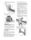
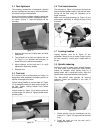
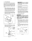
8.1 Headstock sliding
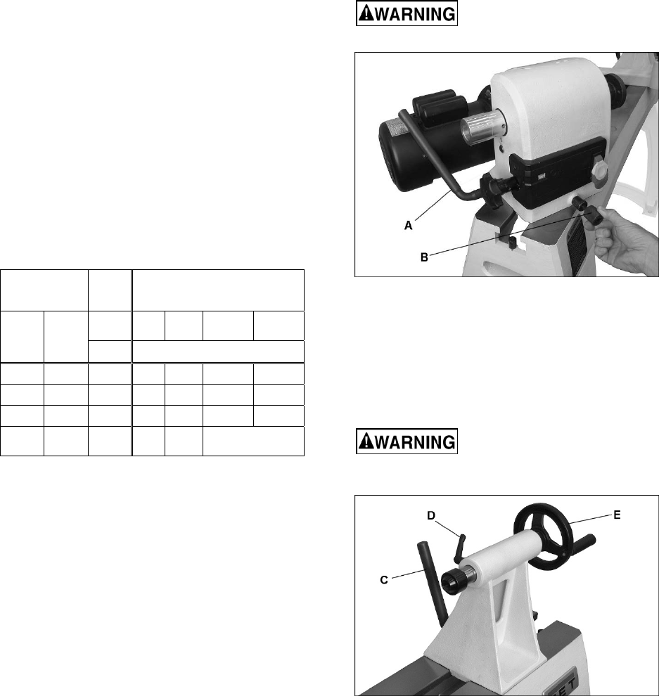
Push handle (A, Figure 9) toward motor to unlock.
Headstock will slide freely along the length of the
bed. Retighten handle before operating lathe.
8.2 Headstock rotation
1. Loosen handle (A, Figure 9).
2. Unscrew the knurled knob (B) counter-
clockwise until it can be pulled outward.
3. Pull knob outward and rotate headstock to
desired position. The headstock has seven
positive locking positions. NOTE: Be careful
not to pinch your fingers against the bed as
you rotate the headstock.
4. Release knob (B) and it will seat itself with an
audible click when the headstock reaches a
positive lock position.
5. Tighten handle (A) by pulling it away from the
motor.
6. Rotate knob (B) clockwise until it engages the
threads.
Always tighten handle (A)
firmly before operating lathe.
Figure 9
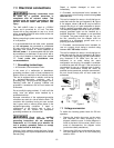
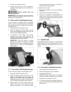
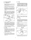
8.3 Tailstock movement
To slide tailstock, push locking handle (C, Figure
10) down toward the bed. Push locking handle
upright to lock tailstock in position.
To move the quill, loosen the lock handle (D) and
rotate the handwheel (E).
Make sure tailstock is locked
to bed (C, Figure 10) and quill is tightened (E)
before turning a spindle on the lathe.
Figure 10
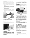
To remove headstock, tailstock or toolrest base
from bed, unscrew and remove either of the studs
(see N, Figure 3). After remounting these items on
the lathe, reinstall studs.
For most turning operations, except outboard
turning, the headstock is positioned at the left end
of bed, and the tailstock moved to accommodate
the workpiece.