


12
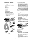
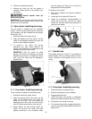
8.4 Cam tightness
The clamping mechanisms of headstock, tailstock
and tool rest base are pre-set by the manufacturer,
and should not require adjustment.
If one of them does not tighten properly against the
bed when the locking handle is tightened, adjust it
as follows. (Figure 11 uses the tailstock as the
example.)
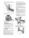
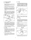
Figure 11
1. Remove stud from end of lathe bed, and slide
tailstock off.
2. Turn tailstock on its side, and tighten lock nut
(F, Figure 11) to increase cam pressure, or
loosen the nut to relieve cam pressure.
3. Mount tailstock on bed and lock it to verify
adjustment. Repeat as needed.
4. Reinstall stud.
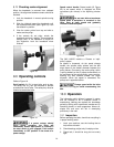
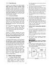
8.5 Tool rest
A 12-inch tool rest is provided with your lathe. It is
designed to allow adjustment for height, position on
the bed, and angle to the work.
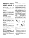
Loosen locking handle on tool rest base (G, Figure
12) to slide base forward or back, and to angle it to
the bed. Tighten locking handle firmly before
operating lathe.
Loosen handle (H, Figure 12) to raise or lower tool
rest and angle it to the work. Tighten handle before
operating lathe.
Figure 12
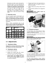
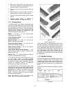
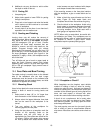
8.6 Tool rest extension
The extension (J, Figure 13) mounts to the tool rest
base and offers greater reach for the tool rest when
turning off the bed using the headstock at an
angle, as shown.
Make sure the clamp bushings (K, Figure 13) are
pulled apart sufficiently to accept the post of the
extension.
Figure 13
8.7 Locking handles
Locking handles, such as H, Figure 12, are
adjustable. Simply lift out on handle, rotate it on the
pin, then release it, making sure it seats itself on
the pin.
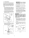
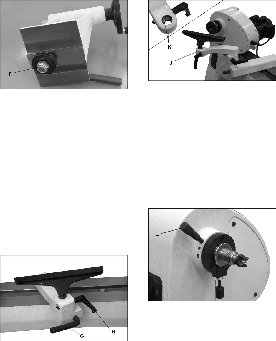
8.8 Spindle indexing
Indexing is used to create evenly spaced features
in a work piece, while keeping the lathe spindle
locked; for example, when cutting flutes on a
spindle blank with a hand-held router, while the
spindle blank is secured between lathe centers.
The JWL-1440VS lathe provides 36 indexing
positions. These are identified in the chart in
section 15.0.
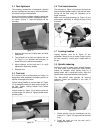
Figure 14
1. Rotate spindle using the handwheel until the
index pin (L, Figure 14) aligns with the desired
hole.
2. Screw the index pin into the hole until it
engages the spindle.