


19
Adjustments
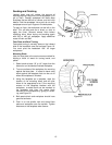
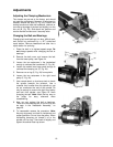
Adjusting the Clamping Mechanism
The clamps are pre-set at the factory and should
not need any adjustment. However, if adjustment is
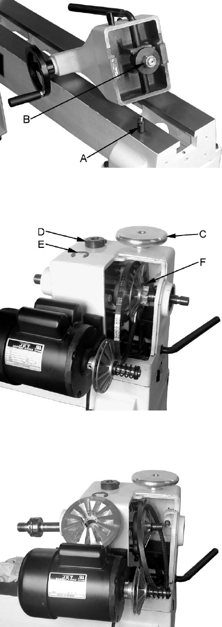
needed, remove the stud (A, Fig. 23). Loosen the
locking handle and slide the headstock, tailstock or
tool rest to the edge of the bed and slightly turn the
hex nut (B, Fig. 23). Slide back into position and
test the handle to make sure it securely locks.
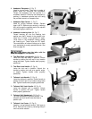
Changing the Belt and Bearings
Changing belt and bearings can be a difficult task,
and should be performed by a JET authorized
repair station. Remove headstock and take into a
repair station for servicing.
1. Place the belt in its highest speed range. Do
not change speeds while changing the belt or
bearings.
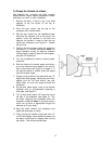
2. Remove the belt cover, and remove the belt
from the lower pulley, see Figure 24.
3. Loosen the two setscrews in the handwheel
enough to unthread the handwheel (C, Fig. 24).
4. Loosen the socket head cap screw enough to
unthread the clamping nut (D, Fig. 24).
5. Remove one e-ring (E, Fig. 24) from spindle.
6. Loosen the two setscrews in the right hand
pulley (F, Fig. 24).
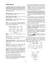
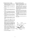
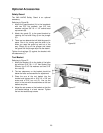
7. Use a wood dowel, or aluminum stock to knock
the spindle towards the tailstock. Use a
material that is softer than the spindle so you
do not mushroom the end of the spindle. Go
only far enough to remove the right hand pulley
and belt from spindle, see Figure 25 when
changing the belt. Note: Mark the key way on
the pulley for easy reference when
reassembling.
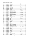
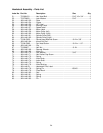
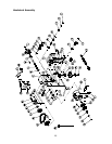
8. Now you can replace the belt or bearings.
There are three bearings #6, 9 and 43 that can
be seen in the “Headstock Assembly,” on
page 25.
9. To reassemble reverse the procedure. Note:
Key way alignment is critical for installment and
proper operation. Do not force the pulley. When
reinstalling clamping nut thread it on to the
spindle until its snug. Then back off slightly and
tighten the socket head cap screw.
Figure 23
Figure 24
Figure 25