


4/29/03
Manual V-16, V-24, VH-24, V-40 & VH-40 13 – Section I
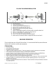
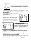
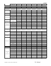
4: Insert the mounting stud (B) into the guide casting (A). Keep the stud
flush with the front of the casting. Keeping the mounting stud flat area
on the bottom, tighten securely the set screw (C) on the bottom of the
casting.
5: Insert this stud and guide assembly into the 7/16” hole in the guidepost. Make sure upper roller guide
is plumb with the guidepost. Lightly tighten set screw you installed in the guidepost.
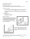
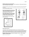
Lower Guide Installation:
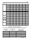
6: Remove lower blade guide. Replace this guide with the high
speed guide containing the
mounting bracket with slotted hole, reusing existing nuts /
bolts.
Position assembly upward along the slotted bracket, so that
the guide body casting has enough clearance to allow the
work table to be tilted for angle cutting. Tighten the socket
head cap screw or nut.
Note: Make certain that if a socket head cap screw is
used, it does not bottom out into the main saw casting
item 1. Shorten the cap screw if necessary
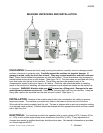
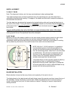
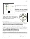
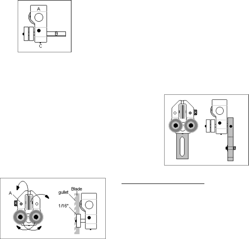
7: Alignment of Upper / Lower Guides:
With blade properly tensioned and tracked, position the
back-up roller by loosening the set
screw (A) on the front of the guide casting, and move the
knurled knob left to right until blade is in alignment with
the groove in the bearing. Rotate the knurled knob until
you have approx. 1/16” clearance from the back of the
blade to the front edge of the back-up roller. Tighten set
screw (A).
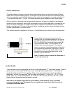
The two roller bearings below the back up bearing can
be adjusted in and out, left and right. Loosen the set screws that retain the bearing stems into the
casting. Using the single bearing assembly, position these bearings approx. 1/16” behind the deepest
gullet of the blade.
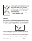
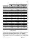
The single bearing assembly along with the adjustably of the upper guide roller will service blades from
¼” to ¾” The double roller set is used only when blade of ½” to 1” are used. Note: The adjustments
are the same for both single and double bearing assemblies.
Rotate eccentric bearing stems until both blade and the back up bearing groove are parallel with each
other. Set screws should be just snug up until actual alignment is confirmed.