


4/29/03
Manual V-16, V-24, VH-24, V-40 & VH-40 25 – Section I
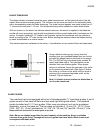
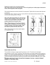
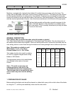
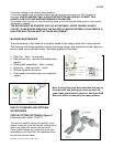
RIP FENCE Standard all models (figure 2)
(Part number 714805 – Model 24/40)
(Part number 714869 – Model 16)
Used for cutting material in accurate straight lines. To attach,
insert T-bolt provided in the T-slot in the front of the table.
Slide into the desired position and tighten handle.
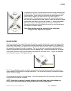
PROFILE CUTTING ATTACHMENT Standard on VH-24 / VH-40 models (figure 3)
(Part number 714821)
This device is used for cutting irregular shapes with the
use of the hydraulic table. Set the chain up as shown
in figure 3. Set the material in the holder and guide
with the hand wheel on the right side of the table. The
excess chain should be coiled out of the way, while
operating the machine.
Note: When chain is not engaged in the rear
sprocket the angle of cut is controlled by guiding
the handles on the holder.
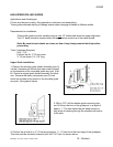
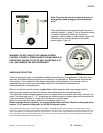
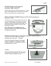
PROTRACTOR HEAD Standard on 24/40 models. Optional for 16 models (figure 4)
(Assembly Part number 714800 24/40 Models)
(Assembly Part number 75561 16 Models)
Used for cutting angles 90 degrees to 45 degrees
in relation to the blade. It is fastened to the table
by means of T-bolts. The L-shaped bar is used for
additional support of the work.
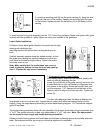
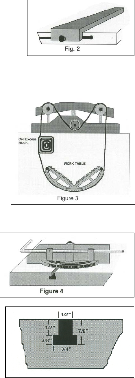
T-SLOTS
T-slots are machine into the work table for your use
with fixturing or other accessories. The dimensions
of these T-slots are furnished to the right.