


4/29/03
Manual V-16, V-24, VH-24, V-40 & VH-40 21 – Section I
38 353 40%
HYDRAULIC FEED TABLE
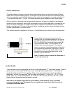
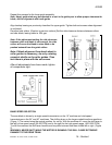
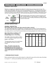
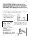
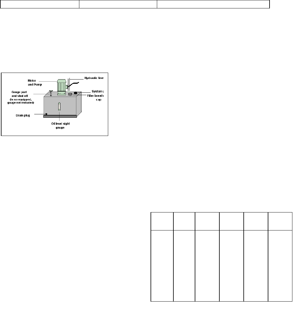
Machines equipped with a hydraulic feed table (VH models) have a pumping unit in the base. The
system has an adjustable relief valve, which is factory preset at 400 p.s.i. This setting may be reduced
to afford greater sensitivity for cutting soft or thin materials. Pressures may be lowered by turning the
square nut located on the top right hand side of the reservoir. (See below graphic) The systems oil level
must be checked periodically to assure the oil levels are maintained at the full level of the sight glass.
The feed table regulator will provide a smooth movement to the
table. If the feed appears to be intermittent it is probably due to
air in the system. This is normally exhausted by running the table
in and out a few times.
WELDING INSTRUCTIONS
GENERAL DESCRIPTION
Note: Always wear eye protection when using this welder or grinder!
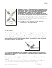
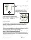
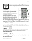
Your Dake vertical band saw is equipped with a “resistance-type” butt welder. The two clamp jaws of
the welder hold the blade ends together. When the welding start knob is turned fully clockwise past the
zero setting, electric current flows through the blade ends creating enough heat to soften and join them.
Note: This welder is suitable to weld
Metal blades 3 x 0.5 - 25 x 0.8mm
bi-metal blades 6 x 0.9 - 25 x 0.9mm
This welder should not be used for welding
2% and 3% tungsten-alloyed metal cutting
blades or HSS blades.
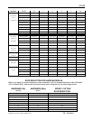
The approximate valves for bi-metal blades
are indicated in the matrix in the next
column
.
Note: * The weld current step and
upsetting pressure step have to be
increased with some saw manufactures.
The saw blade has to be metallically clean
and no tooth may enter into the welding
seam.
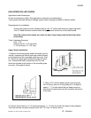
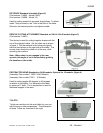
1. PREPARATION OF BLADE
Before welding the blade ends should be cleaned or rubbed with emery cloth on both sides of the blade
to a length of 1”, until they are metallically clean over the enter width.
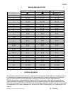
BANDSAW WELDING
CURRENT
UPSETTING
PRESSURE
UPSETTING
WAY
ANNEALING ANNEALING
mm step *) step *) mm COLOR TIME SEC.
6 x 0.9 1 - 2 1 2.5 DARK RED 15
10 x 0.9 1 - 2 1 3.0 DARK RED 15
12 x 0.6 1 - 2 1 3.0 DARK RED 15
12 x 0.9 1 - 2 1 3.0 DARK RED 15
13 x 0.7 1 - 2 1 - 2 3.0 DARK RED 15
16 x 0.7 1 - 2 1 - 2 3.0 DARK RED 15
19 x 0.9 1 - 2 1 - 2 3.0 DARK RED 15
25 x 0.9 1 - 2 1 - 2 3.5 DARK RED 15