


4/29/03
Manual V-16, V-24, VH-24, V-40 & VH-40 14 – Section I
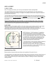
Repeat this process for the lower guide assembly.
Note: Upper guide stud may be adjusted in or out in the guide post to allow proper clearance for
blade, and for alignment with lower guide.
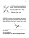
Align backup bearing as previously described for upper guide. Tighten both set screws when alignment
is confirmed.
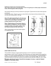
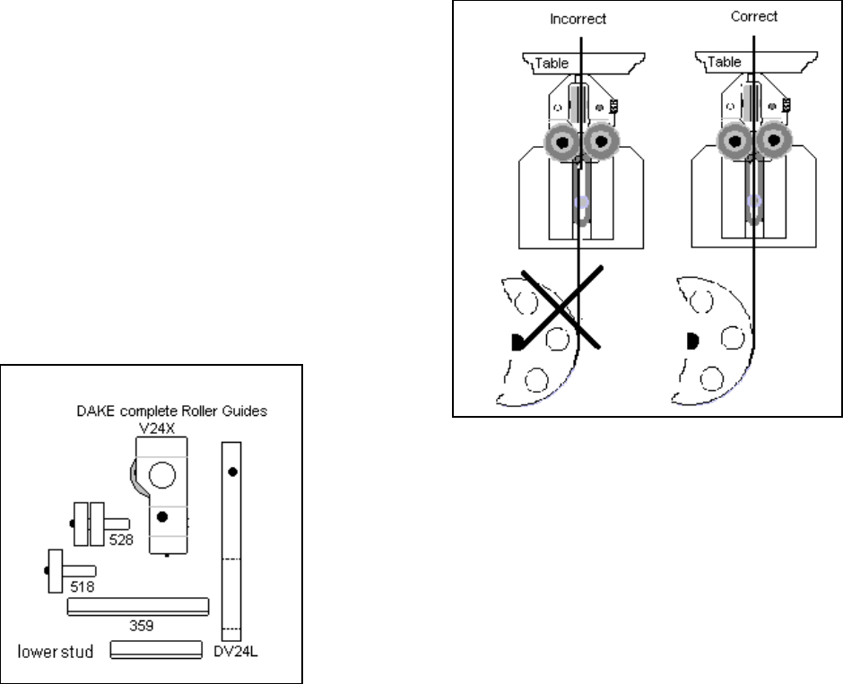
Re-adjust side rollers. (Graphic in previous column) Set the side clearance distance between rollers
and saw blade, leaving about a .004 gap.
Note: If the adjustment setting for side clearance
between roller and blade is not enough, the side
rollers will cause the blade to miss-track or be
pushed outward from the guide rollers.
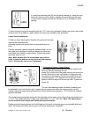
Note: If blade alignment from band wheel to
roller guides is necessary, do so by rotating
eccentric shafts on the roller guides. Then
lock them in place with the set screws.
After all adjustments have been made, tighten
all components tight.
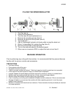
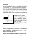
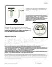
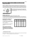
BAND SPEED SELECTION
The saw blade is driven by a single speed transmission on the 16” machine and dual speed
transmissions on the 24” and 40” machines. The shifting lever on the larger models has three positions.
(Figure 1) The center being the neutral position, for set up. With the machine off, move the shift lever to
the left for low speed range (50-500 FPM) and to the right for the high speed range. (500-5000 FPM)
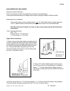
To shift the machine the shift lever handle must be pulled outward and then shifted left or right. (Figure
2)
WARNING: NEVER SHIFT WHILE THE MOTOR IS RUNNING. THIS WILL CAUSE EXTENSIVE
DAMAGE TO THE DRIVE TRAIN.