


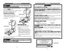
9. Once the cut is completed, turn off the Cut-off saw by releasing the trigger
switch. This also allows the safety button to return to the “OFF” position. See
Figure 8.
10.Unplug the Cut-off saw from the AC power source. Ensure the abrasive wheel
has stopped spinning before removing the workpiece.
11.Use a dry, soft bristle, brush or an air hose and clean any debris remaining
from the cut.
12.Lock down the Cut-off saw with the swing lock handle. Using a pad lock
secure the trigger switch. Store the abrasive Cut-off saw in a dry safe location.
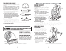
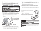
SSEETTTTIINNGG TTHHEE CCUUTT--OOFFFF WWHHEEEELL DDEEPPTTHH GGAAUUGGEE
The cutting depth of the abrasive Cut-off wheel can be
set using the adjustment screw on the wheel housing.
See Figure 13.
1. Locate the depth adjustment screw.
2. Adjust the screw counterclockwise to increase the
depth of cut. Tighten the jam nut.
3. Loosen the jam nut and turn the screw clockwise to
decrease the depth of cut. Tighten the jam nut.
FFoorr ccuuttttiinngg sseeccttiioonnss ooff tthhee wwoorrkkppiieeccee ccoommpplleetteellyy ooffff,,
eennssuurree tthhee ddeepptthh aaddjjuussttmmeenntt ssccrreeww iiss sseet
t aalllloowwiinngg tthhee aabbrraassiivvee CCuutt--ooffff wwhheeeell
ttoo ggoo bbeeyyoonndd tthhee bbaassee ssuurrffaaccee iinnttoo tthhee ggrroooovvee pprroovviiddeedd..
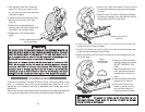
LLAASSEERR GGUUIIDDEE
Use of controls or procedures, or performance of proce-
dures other then those specified herein may result in hazardous radiation
exposure.
1. Release the trigger switch turning the saw off.
2. Place a padlock, with a shank diameter of 13/16" (21mm) or less, through the hole in
the trigger and close it. This makes the trigger switch inoperable. See Figure 11.
3. Place the key for the padlock in a secure location.
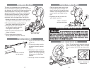
UUSSIINNGG TTHHEE CCUUTT--OOFFFF SSAAWW
DDiissccoonnnneecctt tthhee aabbrraassiivvee CCuutt--ooffff ssaaww ffrroomm tthhee AACC ppoowweerr ssoouurrccee eelliimmiinnaattiinngg
aannyy aacccciiddeennttaall ssttaarrttiinngg ooff t
thhee mmoottoorr..
BBeeffoorree uussiinngg tthhee ssaaww,, eennssuurree tthhee wwhheeeell hhaass ccoooolleedd ddoowwnn ffrroomm aannyy pprreevviioouuss
aaccttiioonnss.. WWeeaarr aappp
prroovveedd lleeaatthheerr wwoorrkk gglloovveess wwhheenn hhaannddlliinngg tthhee vvaarriioouuss
wwoorrkkppiieecceess aanndd ttoo pprrootteecctt tthhee hhaannddss ffrroomm aa hhoott C
Cuutt--ooffff wwhheeeell..
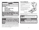
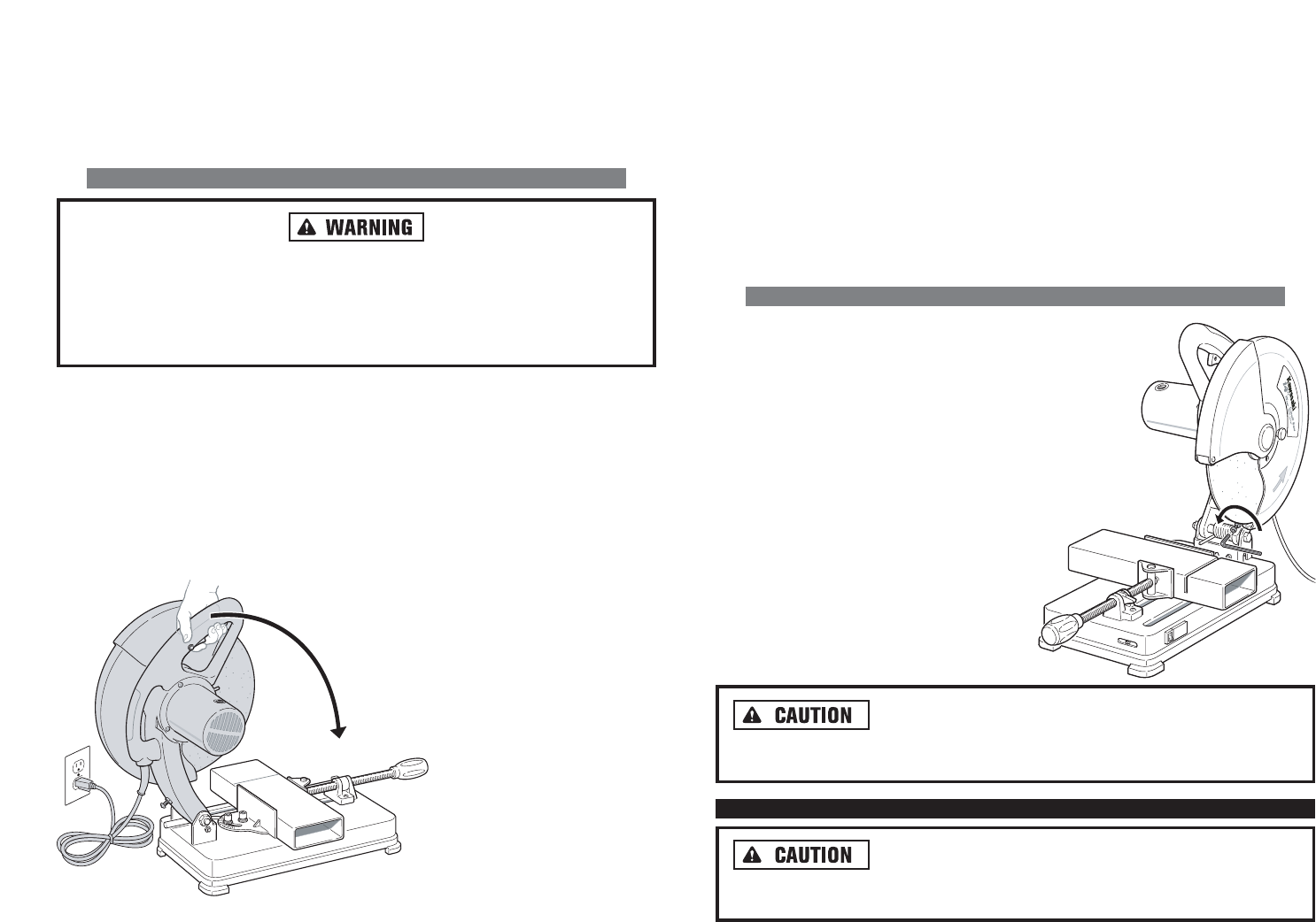
FFOOLLLLOOWW TTHHEE IINNSSTTRRUUCCTTIIOONNSS BBEELLOOWW TTOO OOPPEERRAATTEE TTHHEE AABBRRAASSIIVVEE CCUUTT--OOFFFF
SSAAWW.. SSEEEE FFIIGGUURREE 1122..
1. Adjust the angle of cut. See ADJUSTING THE WORK VISE on pages 15-16.
2. Turn the screw clamp clockwise to securely tighten the workpiece in the vise.
3. Plug the power cord into an approved GROUNDED AC receptacle.
4. Grip the handle and place thumb over the safety button.
5. Press the safety button with thumb. Squeeze the trigger switch. Release the
safety button.
8. Ensure the abrasive Cut-off wheel cuts completely through the workpiece.
Should the Cut-off wheel fail to pass through the workpiece, raise the handle
until it clears. Turn off the Cut-off saw and remove the power cord from the AC
receptacle. Refer to SETTING THE CUT-OFF WHEEL DEPTH GAUGE.
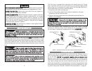
FIGURE 12. USING
THE CUT-OFF SAW
6. Allow the Cut-off saw to spin up to full
speed.
7. Slowly pull down on the handle while
continuing to squeeze trigger switch.
Lower the Cut-off wheel slowly into the
workpiece.
FIGURE 13. SETTING THE
DEPTH GAUGE
20