


3. Using a 5/16" (8mm) hex wrench or hex bit, turn the two hex socket-head cap
screws clockwise to securely tighten.
4. Using a 5/16" (8mm) hex wrench or hex bit, turn the two hex socket-head cap
screws counterclockwise and remove them.
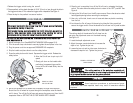
5. Slide the stationary portion of the work vise over the last threaded hole in the
Cut-off saw base.
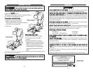
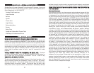
TThhee aanngglleedd ccuutt sseettttiinnggss oonn tthhee ffeennccee bbaassee aarree oonnllyy
aapppprrooxxiimmaattee sseettttiinnggss.. AAllwwaayyss cchheecckk tthhee aaccccu
urraaccyy ooff aanngglleedd ccuutt sseettttiinnggss
uussiinngg aa pprroottrraaccttoorr oorr bbeevveell ggaauuggee..
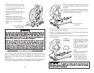
5. Hold the arbor shaft lock in place and
use a 5/16" (8mm) hex wrench or hex
bit, turn the hex socket-head cap screw
clockwise to tighten.
6. Tighten the hex socket-head cap screw
securely into the motor arbor. See
Figure 4.
7. Replace the movable blade guard
exposing the covering hex socket-head
cap screw for the abrasive wheel.
8. Replace nut on the movable blade
guard.
DDoo nnoott oovveerr ttiigghhtteenn tthhee hheexx ssoocckkeett--hheeaadd ssccrreeww.. OOvveerr ttiigghhtteenniinngg tthhee ssccrreeww ccaann
ccaauussee tthhee aabbrraas
siivvee wwhheeeell ttoo ccrraacckk rreessuullttiinngg iinn pprreemmaattuurree ffaaiilluurree.. TThhiiss ccoouulldd
ccaauussee tthhee aabbrraassiivvee wwhheeeell ttoo bbrreeaakk aanndd
ffllyy ooffff tthhee aarrbboorr sshhaafftt wwhheenn tthhee ttrriigg--
ggeerr iiss eennggaaggeedd.. FFaaiilluurree ttoo aaddhheerree ttoo tthhiiss WWaarrnniinngg ccoouulldd ccaauusse
e ddaammaaggee ttoo tthhee
CCuutt--ooffff ssaaww aanndd sseevveerree iinnjjuurryy oorr eevveenn ddeeaatthh ttoo tthhee ooppeerraattoorr..
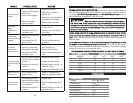
UUssee oonnllyy aa 1144"" ddiiaammeetteerr aabbrraassiivvee CCuutt--ooffff wwhheeeell rraatteedd ttoo aa mmiinniimmuumm 44000000
RRPPMM.. CCuutt--ooffff wwhheeeellss tthhaatt ddoo nnoott mmaattcchh tthhee mmoouunnttiinngg hha
arrddwwaarree,, eexxcceeeedd aa
mmaaxxiimmuumm 44440000 RRPPMM oorr ffaallll bbeellooww tthhee mmiinniimmuumm 44000000 RRPPMM mmaayy ssuussttaaiinn
pprreemmaattuurree wweeaarr oorr
bbrreeaakkaaggee aanndd ffllyy ooffff tthhee CCuutt--ooffff ssaaww oorr rruunn eecccceennttrriiccaallllyy
rreessuullttiinngg iinn aa lloossss ooff ccoonnttrrooll.. FFaaiilluurree tto
o aaddhheerree ttoo tthhiiss WWaarrnniinngg ccoouulldd ccaauussee
ddaammaaggee ttoo tthhee CCuutt--ooffff ssaaww aanndd sseevveerree iinnjjuurryy oorr eevveenn ddeeaatthh ttoo tthhe
e ooppeerraattoorr..
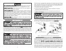
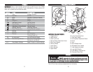
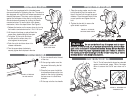
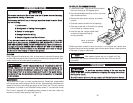
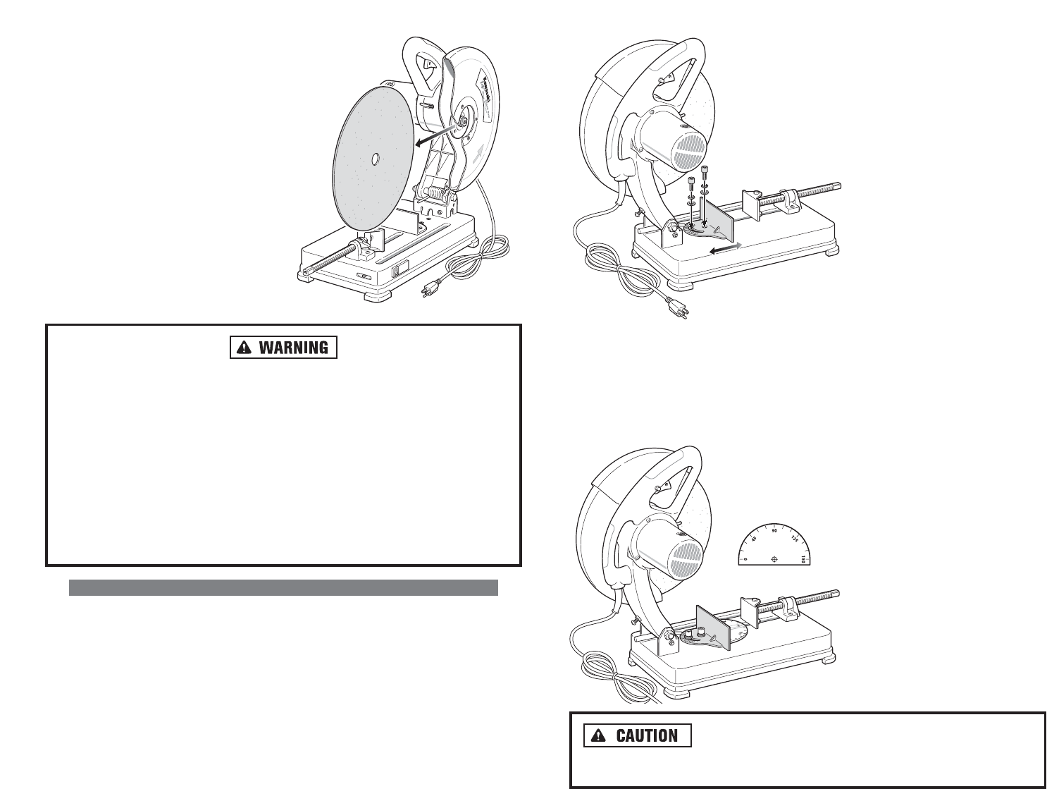
AADDJJUUSSTTIINNGG TTHHEE WWOORRKK VVIISSEE
The work vise is located on the base of the Cut-off saw. The vise is made up of two
parts: (1) a stationary fence which can be loosened and rotated from 0˚ to 45˚
degrees and (2) a movable clamp with an adjustable screw handle and a quick-
release lock.
The work vise will also move toward the rear of the base to allow larger workpieces to be
cut. To set up and adjust the work vise, follow the directions below. See Figure 6.
15
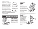
FIGURE 5. REMOVING/INSTALLING
THE CUTTING WHEEL
FIGURE 6. ADJUSTING THE
WORK VISE
1. Using a 5/16" (8mm) hex wrench or hex bit, turn the
two hex socket-head cap screws counterclockwise
to loosen.
2. Rotate the work vise fence to the desired the angle
by aligning the gauge on the vise base with the indi-
cator groove in the Cut-off saw base.
FIGURE 7.
CHECKING ANGLE
CUT SETTINGS
6. Install one of the hex socket-
head cap screws into the hole.
DO NOT TIGHTEN AT THIS
TIME.
7. Align the second hole of the
work vise base with another
threaded hole in the Cut-off
base.
8. Install the second hex socket-
head screw into the hole.
9. Using a 5/16" (8mm) hex
wrench or hex bit, turn the
two hex socket-head cap
screws clockwise to loosen.