


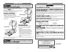
RREEMMOOVVIINNGG AANNDD IINNSSTTAALLLLIINNGG TTHHEE AABBRRAASSIIVVEE CCUUTTTTIINNGG WWHHEEEELL
RREEMMOOVVIINNGG TTHHEE AABBRRAASSIIVVEE
CCUUTTTTIINNGG WWHHEEEELL::
1. Raise the abrasive wheel to its full open
position.
2. Remove the Stop Knob on the movable
blade guard.
3. Remove the movable blade guard
exposing the attaching hex socket-head
cap screw for the abrasive wheel.
4. Set the movable guard aside ensuring that it
doesn’t get bent or distorted.
5. Push the arbor shaft lock lever
and rotate the abrasive wheel until
the arbor lock engages locking
the wheel in place.
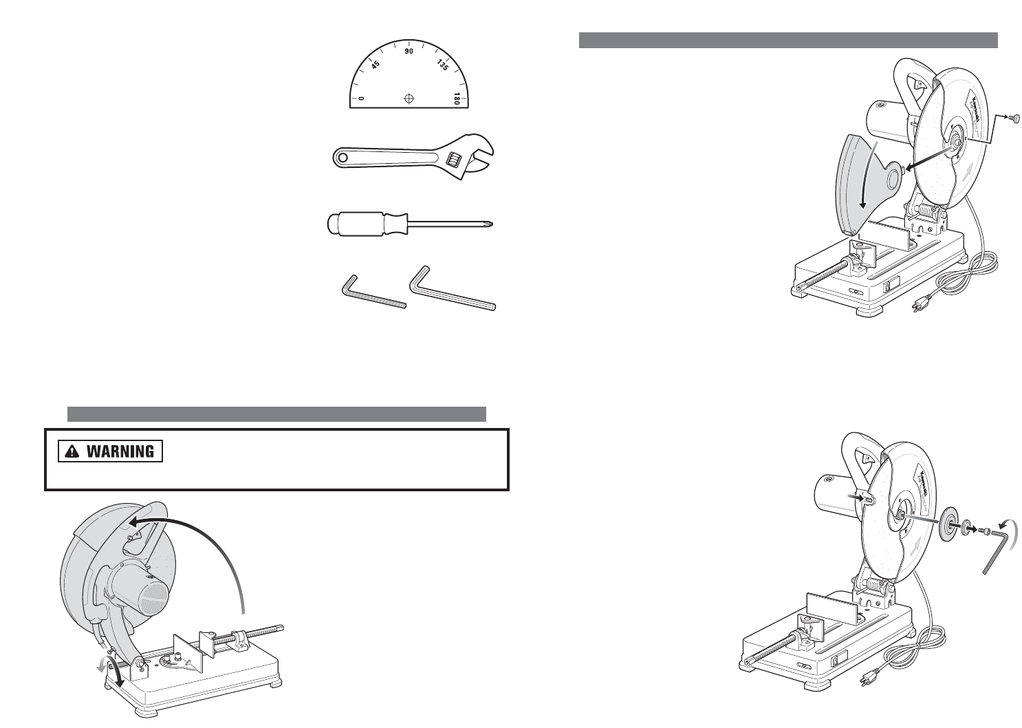
6. Hold the arbor shaft lock in
place and use a 5/16" (8mm) hex wrench or hex bit, remove the hex socket-head cap
screw by turning it counterclockwise. Also, remove the washer, outer flange, arbor
adapter (if used), abrasive wheel, and inner flange. See Figure 4.
IINNSSTTAALLLLIINNGG TTHHEE AABBRRAASSIIVVEE
CCUUTTTTIINNGG WWHHEEEELL::
1. Place the hex socket-head cap
screw, washer, outer flange and
arbor adapter (if used) through the
hole in the new abrasive wheel.
2. Place the inner flange onto the
screw protruding to the back side
of the new abrasive wheel.
3. Holding the new abrasive wheel in
one hand, align the screw into the
threaded hole in the arbor.
4. Push in the arbor shaft lock
lever and turn the new
abrasive wheel until the
shaft locks.
13
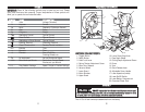
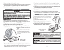
TTOOOOLLSS RREEQQUUIIRREEDD FFOORR AASSSSEEMMBBLLYY
The tools, pictured, are supplied by the
customer.
It is highly recommended that the 14" Cut-off
saw be securely mounted to a tool stand. This
is to prevent excessive vibration during use.
Mount the Cut-off saw to the tool stand by:
1. Most tool stands have pre-drilled holes to
accommodate a variety of tools.
2. If the tool stand does not have an exact
match for the holes, try to align the tool
base with as many pre-drilled holes as pos-
sible. Mark and drill new holes for mounts
that have missing holes.
3. Insert four 1/4" X 20 screws and washers
through the underside of the tool stand and
up through the rubber feet on the base of
the Cut-off saw. The length of the screws should be 1" (25mm).
4. Tighten the screws securely.
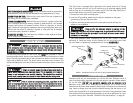
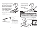
UUNNLLOOCCKKIINNGG TTHHEE CCUUTT--OOFFFF SSAAWW
DDiissccoonnnneecctt tthhee aabbrraassiivvee CCuutt--ooffff ssaaww ffrroomm tthhee AACC ppoowweerr
ssoouurrccee eelliimmiinnaattiinngg aannyy aacccciiddeennttaall ssttaarrttiinngg ooff t
thhee mmoottoorr..
PHILLIPS SCREWDRIVER
ADJUSTABLE WRENCH
PROTRACTOR
HEX (ALLEN) WRENCHES
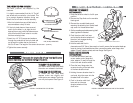
FIGURE 3. REMOVING BLADE GUARD
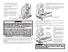
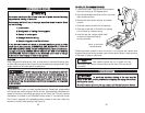
TTOO CCAARRRRYY TTHHEE CCUUTT--OOFFFF SSAAWW::
Fold down head to base and rotate
the motor arm release to lock head.
TTOO UUNNLLOOCCKK TTHHEE CCUUTT--OOFFFF SSAAWW::
To unlock tool and raise head
depress motor arm slightly and
rotate motor arm release. The motor
arm will pivot upward. See Figure 2.
FIGURE 2. UNLOCKING THE CUT-OFF SAW
LOCK
RELEASE
14
FIGURE 4. REMOVING/INSTALLING THE CUTTING WHEEL