


Kramer Electronics Ltd.
12
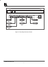
6 INSTALLATION
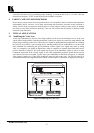
6.1 Rack Mounting
The SG-7 and the SG-6003B can be rack mounted in a standard 19” (1U) EIA rack, and include rack
“ears” at the ends of the front panel. To rack mount these machines, simply place the unit's ears against the
rack rails of your rack, and insert standard screws through each of the four corner holes. The SG-6N, SG-9
and the SG-11 can be rack mounted using a special adapter (see section 4.1). None of these devices require
any specific spacing for ventilation above or below the unit.
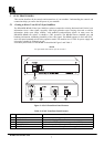
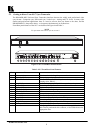
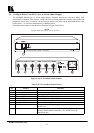
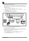
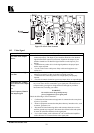
6.2 Connecting To Video Devices
Video sources and output devices (such as recorders) may be connected to the machines through the BNC
type connectors located on the back of the unit. Unused inputs are terminated to 75ohm, and active inputs
should be terminated by the connecting source.
7 USING THE MACHINES
7.1 Powering on the machine
NOTES
The machine should only be powered on, after all connections are
completed, and all source devices have been powered on. Do not attempt to
connect or disconnect any video to the machine while it is powered on!
The socket-outlet should be near the equipment and should be easily
accessible. To fully disconnect equipment, remove power cord from socket.
1) Press the power switch on the machine's front panel and verify that it glows.
2) Operate the acceptors.
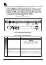
7.2 NTSC/PAL Selection (SG-6N only)
There are several different video standards used in different countries. The leading standards are PAL,
used in most European countries, NTSC used in the US, in Japan and some other countries and SECAM,
which is used mainly in France, and some other countries. Each standard uses different color encoding
schemes. Sync related problems might be encountered during NTSC or PAL operation include:
1) Problems with the sync information carried along with the video signal.
2) Problems of sync signal compatibility with the users’ system.
To select PAL or NTSC, simply select the required system using the
NTSC/PAL
switch located on the
rear panel (pressed =
NTSC
).
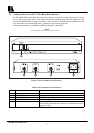
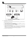
7.3 Looping (SG-7 only)
The looping function enables the operator to connect several machines to a video source. The operator
must always switch the termination switch of the
first
and
middle
machines to "
Hi-z
". The
last
machine's
termination switch should always be at "
75ohm
" to maintain well-matched lines (of 75ohm impedance)
from the first to the last machine. If the looping function is not used, the termination switch should be set
to "
75 ohm
".
7.4 Clamping (SG-11 only)
Clamping is an electronic process which corrects line-by-line the video blanking level or "
sync tip"
by
clamping it to a predefined DC level. The process reduces the DC level changes when switching between
different sources, eliminates picture jumps on the screen, the accumulation of low frequency noise and
instability. Clamping also increases the dynamic range of video devices by limiting the average picture
changes, which stress the video device. When dealing with composite video signals, it is recommended to
perform DC clamping to -1V and RGB signals should be clamped to 0V. Unwanted DC offsets can also be