


A-5
INSTALLATION
RANGER 3 PHASE
A-5
• Duty Cycle is the percentage of time the load is
being applied in a 10 minute period. For example, a
60% duty cycle represents 6 minutes of load and 4
minutes of no load in a 10 minute period. Duty Cycle
for the RANGER 3 PHASE is 100%.
AUXILIARY POWER
Do not connect any plugs that connect to the
power receptacles in parallel.
------------------------------------------------------------------------
Start the engine and set the “IDLER” control switch to
the “High Idle” mode. Set the “CONTROL” to 10.
Voltage is now correct at the receptacles for auxiliary
power. This must be done before a tripped GFCI
receptacle can be reset properly. See the MAINTE-
NANCE section for more detailed information on test-
ing and resetting the GFCI receptacle.
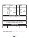
The RANGER 3 PHASE can provide both three phase
and single phase power, up to 11,500 watts of 480
volts AC, three phase 60Hz power for peak use, and
up to 10,500 watts of 480 volts AC, three phase 60Hz
power for continuous use, up to 10,500 watts of
120/240 volts AC, single phase 60Hz power for peak
use, and up to 9,500 watts of 120/240 volt AC, single
phase 60Hz power for continuous use. The front of
the machine includes four receptacles for connecting
the AC power plugs; one 20 amp 480 volt 3 phase
NEMA receptacle, one 50 amp 120/240 volt NEMA
14-50R receptacle and two 20 amp 120 volt NEMA 5-
20R receptacles. Output voltage is within +/-10% at all
loads up to rated capacity. Do not use 3 phase power
and single phase power simultaneously.
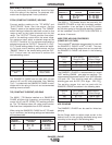
120/240 VOLT DUAL VOLTAGE RECEPTACLE
The 120/240 volt receptacle can supply up to 40 amps
of 240 volt power to a two wire circuit, up to 40 amps
of 120 volts power from each side of a three wire cir-
cuit (up to 80 amps total). Do not connect the 120 volt
circuits in parallel. Current sensing for the automatic
idle feature is only in one leg of the three wire circuit
as shown in the following column.
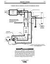
CONNECTION OF THE LN-25 TO THE RANGER 3
PHASE
• Shut the welder off.
•
Connect the electrode cable from the LN-25 to
the
“ELECTRODE” terminal of the welder.
Connect the work cable to the “TO WORK” termi-
nal of the welder.
• Position the welder “Polarity” switch to the
desired polarity, either DC (-) or DC (+).
• Position the “RANGE” switch to the “WIRE
FEED” position.
• Attach the single lead from the LN-25 control box
to the work using the spring clip on the end of the
lead - it carries no welding current.
• Place the engine switch in the “AUTO” position.
• Adjust wire feed speed at the LN-25 and adjust
the welding voltage with the output “CONTROL”
at the welder.
NOTE: The welding electrode is energized at all
times, unless an LN-25 with built-in contactor is used.
If the output “CONTROL” is set below “3”, the LN-25
contactor may not pull in.
CONNECTION OF K930-2 TIG MODULE TO THE
RANGER 3 PHASE.
The TIG Module is an accessory that provides high
frequency and shielding gas control for AC and DC
GTAW (TIG) welding. See IM528 supplied with the
TIG Module for installation instructions.
Note: The TIG Module does not require the use of a
high frequency bypass capacitor. However, if the
RANGER 3 PHASE is used with any other high fre-
quency equipment, the bypass capacitor must be
installed, order kit T12246.
INSTRUCTIONS
ADDITIONAL SAFETY PRECAUTIONS
Always operate the welder with the roof and case
sides in place as this provides maximum protection
from moving parts and assures proper cooling air
flow.
Read and understand all Safety Precautions before
operating this machine. Always follow these and any
other safety procedures included in this manual and in
the Engine Owner’s Manual.
WELDER OPERATION
WELDER OUTPUT
• Maximum Open Circuit Voltage at 3700 RPM is
80 Volts RMS.
RANGER 3 PHASE
Constant Current 225 Amps AC @ 25 Volts
210 Amps DC @ 25 Volts
Constant Voltage 200 Amps DC @ 20 Volts
CAUTION