


A-5
INSTALLATION
PRECISION TIG 225
A-5
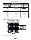
INPUT RECONNECT PROCEDURE
On multiple input voltage welders, be sure the
machine is connected per the following instructions
for the voltage being supplied to the welder.
Failure to follow these instructions can cause
immediate failure of components within the welder
and void machineʼs warranty.
-----------------------------------------------------------------------
Multiple voltage models are shipped connected
for the highest voltage. To change this connection
refer to the following instructions.
ELECTRIC SHOCK can kill.
• Turn the input power OFF at the dis-
connect switch or fuse box before
working on this equipment.
------------------------------------------------------------------------
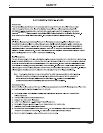
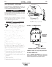
For the lowest rated voltage connection (Refer to figure A.1):
1. Remove the sheet metal left side cover.
2. Disconnect lead H3 from the power switch and
insulate with the insulation from the H2 lead.
3. Connect lead H2 to the power switch where H3 was
connected.
4. Tighten connections.
5. Replace sheet metal cover and all screws
For the highest rated voltage connection (Refer to figure A.1):
The machine is normally shipped connected for the
highest rated voltage, however verify the following:
1. Remove the sheet metal left side cover.
2. Disconnect lead H2 from the power switch and
insulate with the insulation from the H3 lead.
3. Connect lead H3 to the line switch where H2 was
connected.
4. Tighten connections.
5. Replace sheet metal cover and all screws.
CONNECTIONS FOR TIG (GTAW) WELDING
TIG TORCH CONNECTION
Refer to Included Equipment in the Operation
Section of this manual for TIG welding equipment
which is included with the PRECISION TIG 225.
CAUTION
WARNING
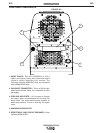
FIGURE A.1 Reconnect Leads
INPUT LEADS INPUT LEADS
L1 & L2L1 & L2
LEAD H1LEAD H1
(DO NOT (DO NOT
REMOVE)REMOVE)
FOR LOWEST RATED VOLTAGEFOR LOWEST RATED VOLTAGE
: H2 CONNECTED: H2 CONNECTED
FOR HIGHEST RATED VOLTAGEFOR HIGHEST RATED VOLTAGE
: H3 CONNECTED: H3 CONNECTED
BACK VIEW OF LINE SWITCHBACK VIEW OF LINE SWITCH
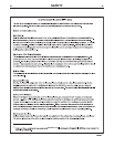
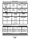
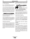
OUTPUT CONNECTIONS
FIGURE A.2 Location of Output Connections
ELECTRODE/GAS
OUTLET
RECEPTACLE
(TWIST-MATE)
WORK CABLE & CLAMP