


B-3
OPERATION
B-3
CONTROL FUNCTIONALITY
1. POWER SWITCH – Input line switch turns input
power ON or OFF, as indicated by the on or off sta-
tus of the front panel digital display (See Item 6,
also see the following page for Power-Up
Sequence).
2. POLARITY SWITCH – The rotary power switch has
3-positions for DC+, AC and DC- selections for the
electrode output stud welding polarity.
• Do not switch the polarity switch
while welding or damage may result
to the machine.
------------------------------------------------------------------------
3. MODE SWITCH – The push button switch allows
selection of the two machine welding modes as
indicated by colored mode lights:
• STICK mode – Top position Red light.
• TIG mode – Bottom position Green light.
4. AC BALANCE CONTROL – The potentiometer
control permits AC TIG wave balance adjustment
from Max. Penetration (~80% negative wave) at full
CW rotation setting, to CCW rotation Max. Cleaning
(~60% positive wave), and includes:
• Auto Balance position indicated by the Green panel
light turning on. This feature automatically provides
the proper amount of cleaning and penetration for
normal AC TIG welding.
5. MAXIMUM OUTPUT CONTROL – Presets the out-
put welding current over the rated output range of
the machine:
• With a Remote Current Control (Amptrol) connect-
ed to the Remote Receptacle (See item 10), this
knob sets the Maximum output current level set
table with the remote Amptrol.
• For Pulse TIG (See Item 8) this knob sets the
Peak Pulse level, with the Remote Amptrol (if
used).
6. DIGITAL METER – A 3 digit LED meter is used to
display the preset output current level before weld-
ing, and actual output level while welding:
• A lit display indicates input power is turned on.
(See Item 1).
7. POST FLOW TIME – Sets the TIG mode shielding
gas post flow time over the range of about 1 to 30
seconds after the arc is shut off.
Note: Gas preflow time is fixed at 0.5 second only in
TIG mode, but no preflow time will occur if the arc is
restarted
during Post Flow time, since shielding gas
would not have stopped flowing.
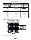
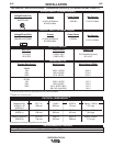
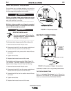
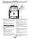
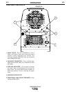
PRECISION TIG 225
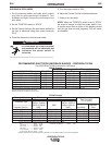
CONTROLS AND SETTINGS
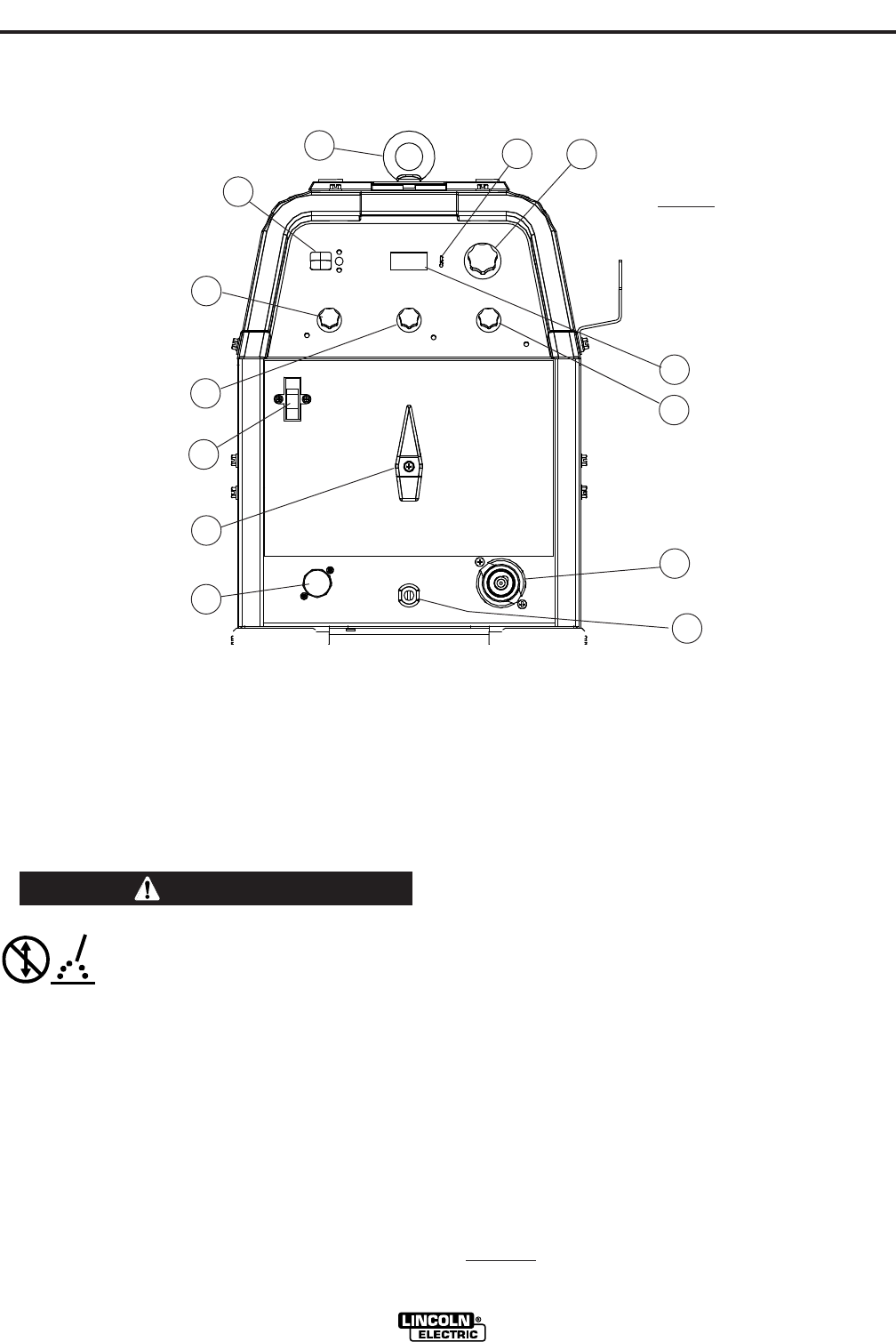
All operator controls and adjustments are located on the front of the PRECISION TIG 225. Refer to Figure B.1
and corresponding explanations.
FIGURE B.1 - CONTROL PANEL
1. POWER SWITCH
2. POLARITY SWITCH
3. MODE SWITCH
4. AC BALANCE CONTROL
5. MAXIMUM
OUTPUT CONTROL (AMPS)
6. DIGITAL METERS
7. POST FLOW TIME
8. PULSE TIG CONTROL
9. THERMAL SHUTDOWN LIGHT
10. REMOTE RECEPTACLE
11. ELECTRODE/GAS OUTPUT
RECEPTACLE
12. WORK CABLE
13. REMOVABLE LIFT EYEBOLT
5
13
2
6
3
4
1
7
9
10
11
12
8
CAUTION