


F-2
DIAGRAMS
F-2
WELDMARK 225
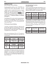
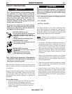
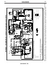
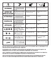
CONNECTION OF WELDMARK 225 TO LN-7 & K240 CONTACTOR KIT
WARNING: Turn the power off when making connections.
N.A. Use power source polarity switch to set for desired elec-
trode polarity. Position the output selector switch on the
power source to the CV position.
N.B. 3 conductor #16 power cord physically suitable for the
installation and plug rated at 115 volts 15 amperes AC.
N.C. Plug into 115 volt AC receptacle on welder control panel or
other 115 volt AC supply rated at a minimum of 500 volt-
amperes.
N.D. Leads #21 and GND do not appear on LN-7’s with codes
below 7026.
N.E. Welding cables must be of proper capacity for the current
and duty cycle of immediate and future applications.
N.F. If LN-7 is equipped with a meter kit, extend lead #21 using
#14 or larger insulated wire physically suitable for the
GND. 32 2 4 31
TO LN-7
32
2
4
31
POWER
SOURCE
AUTO.
EQUIP.
WORK
ELECTRODE
POWER
SOURCE
75
76
77
K240 CONTACTOR KIT
21
115V (50/60HZ.)
(NOTE : 600 AMP CAPACITY)
ELECTRODE CABLE TO LN-7
TO WORK
CONTROL CABLE
CONNECT THE CONTROL CABLE
GROUND LEAD TO THE FRAME
THE TERMINAL STRIP OR TO
AN UNPAINTED FRAME SCREW.
N.D.
N.J.
N.F. & N.G.
N.B.
N.C.
TERMINAL MARKED NEAR
CONNECTION OF LN-7 & K240 CONTACTOR KIT WITH 115 VOLT AC AUXILIARY POWER AND CV OUTPUT
WELDER STANDARD OUTPUT TERMINALS
S17742
10-2-92
installation. An S16586-”length” remote voltage sensing
work lead may be ordered for this purpose. Connect it
directly to the work piece independent of the welding work
cable. For convenience, this extended #21 lead should be
taped to the welding work lead.
N.G. Tape up bolted connection where lead #21 is extended.
N.H. Idler switch on power source must be in high idle position.
N.J. If an optional remote output control is used, connect it to
this terminal strip or 6 pin Amphenol receptacle. NOTE:
Terminal strip or 6 pin Amphenol receptacle not available
on all power sources.
CAUTION: Any speed up of the engine RPM by changing the
governor setting or over-riding the throttle linkage will
cause an increase in the AC auxiliary voltage. If this volt-
age goes above 140 volts, the LN-7 control circuit will be
damaged. The engine governor setting is pre-set at the fac-
tory - do not adjust above RPM specifications listed in
engine welder operating manual.
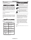
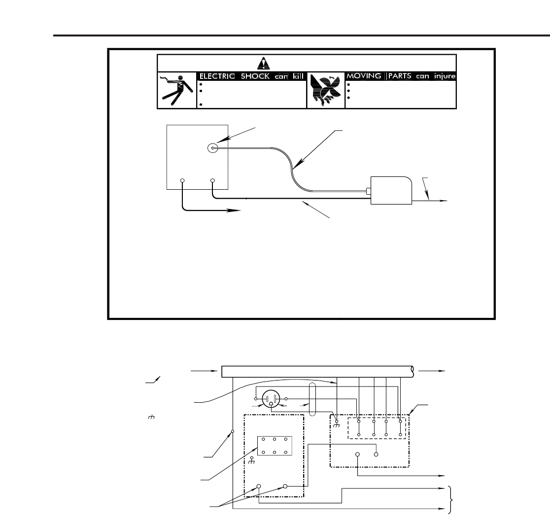
M17486
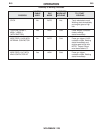
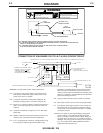
ELECTRODE CABLE
LN-25
WIRE FEEDER
REMOTE CONTROL
TO WORK
ELECTRODE
N.A. WELDING CABLE MUST BE SIZED FOR CURRENT AND DUTY CYCLE OF APPLICATION.
TO WORK
WORK CLIP LEAD
TO WORK
6 PIN
AMPHENOL
N.C. IF OPTIONAL REMOTE OUTPUT CONTROL IS USED, PLACE OUTPUT CONTROL SWITCH
IN "OUTPUT CONTROL REMOTE" POSITION.
WELDMARK 225 / LN-25 ACROSS THE ARC CONNECTION DIAGRAM
CRM 21883
OPTIONAL K444-1
N.B. USE POLARITY SWITCH TO SET FOR DESIRED ELECTRODE POLARITY. POSITION THE OUTPUT SELECTOR
SWITCH TO THE WIRE FEED (CV) POSITION.
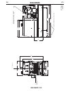
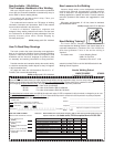
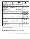
WARNING
Do not operate with panels open.
Disconnect NEGATIVE (-) BATTERY LEAD
before servicing.
Do not touch electrically live parts.
Keep guards in place.
Keep away from moving parts.
Only qualified personnel should install,use
or service this equipment.