


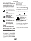
A-5
INSTALLATION
RANGER 250
A-5
When in the CC-STICK, PIPE, and CV-WIRE modes
and when a remote control is connected to the
Amphenol, the auto-sensing circuit in the Ranger 250
automatically switches the OUTPUT control from con-
trol at the welder to remote control .
The 14 pin connector is used to directly connect a
wire feeder or TIG Module (K930-2) control cable. In
the CV-WIRE mode, the Ranger 250 auto-sensing cir-
cuit automatically makes the Ranger 250 Output
Control inactive and the wire feeder voltage control
active when the control cable is connected to the 14
pin connector.
NOTE: When a wire feeder with a built in welding volt-
age control is connected to the 14 pin connector, do
not connect anything to the 6 pin connector.
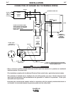
ELECTRICAL CONNECTIONS
MACHINE GROUNDING
Because this portable engine driven welder
creates its own power, it is not necessary to connect
its frame to an earth ground, unless the machine is
connected to premises wiring (home, shop, etc.)
To prevent dangerous electric shock, other equipment
to which this engine driven welder supplies power
must:
1) Be grounded to the frame of the welder using a
grounded type plug.
2) Be double insulated.
Do not ground the machine to a pipe that carries
explosive or combustible material.
------------------------------------------------------------------------
When this welder is mounted on a truck or trailer, its
frame must be securely connected to the metal frame
of the vehicle. When this engine driven welder is con-
nected to premises wiring such as that in a home or
shop, its frame must be connected to the system earth
ground. See further connection instructions in the sec-
tion entitled "Standby Power Connections" as well as
the article on grounding in the latest U.S. National
Electrical Code and the local code.
In general, if the machine is to be grounded, it should
be connected with a #8 or larger copper wire to a solid
earth ground such as a metal water pipe going into
the ground for at least ten feet and having no insulat-
ed joints, or to the metal framework of a building
which has been effectively grounded.
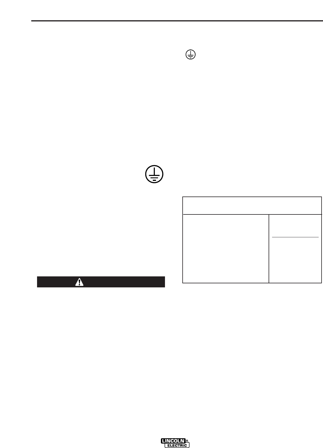
The U.S. National Electrical Code lists a number of
alternate means of grounding electrical equipment. A
machine grounding stud marked with the symbol
is provided on the front of the welder.
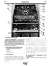
WELDING TERMINALS
The Ranger 250 is equipped with a toggle switch for
selecting "hot" welding terminal when in the "WELD
TERMINALS ON" position or "cold" welding terminal
when in the "REMOTELY CONTROLLED" position.
WELDING OUTPUT CABLES
With the engine off connect the electrode and work
cables to the output studs. The welding process dic-
tates the polarity of the electrode cable. These con-
nections should be checked periodically and tightened
with a 3/4" wrench.
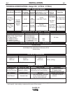
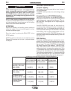
Table A.1 lists recommended cable sizes and lengths
for rated current and duty cycle. Length refers to the
distance from the welder to the work and back to the
welder. Cable diameters are increased for long cable
lengths to reduce voltage drops.
TABLE A-1
CABLE INSTALLATION
Install the welding cables to your RANGER 250 as fol-
lows.
1. The gasoline engine must be OFF to install welding
cables.
2. Remove the flanged nuts from the output terminals.
3. Connect the electrode holder and work cables to
the weld output terminals. The terminals are identi-
fied on the case front.
4. Tighten the flanged nuts securely.
5. Be certain that the metal piece you are welding (the
“work”) is properly connected to the work clamp and
cable.
WARNING
TOTAL COMBINED LENGTH OF
ELECTRODE AND WORK CABLES
Cable Length
0-100Ft. (0-31meters)
100-150 Ft. (30-46 meters)
150-200 Ft. (46-61 meters)
Cable Size for
250 Amps
100% Duty Cycle
1 AWG
1 AWG
1/0 AWG