


B-2
OPERATION
B-2
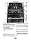
WELDING CONTROLS:
1. OUTPUT CONTROL: The CONTROL dial
provides continuous control of the welding current or
welding voltage depending on the selected welding
mode. This control is not active in the CC-STICK,
PIPE, and CV-WIRE modes when a remote control or
wire feeder with remote control is connected to either
the 6 pin or 14 pin Amphenol.
2. WELD MODE SELECTOR SWITCH:
(Provides four selectable welding modes)
CV-WIRE
PIPE
CC-STICK
TOUCH START TIG
3. ARC CONTROL :
The ARC CONTROL WIRE/STICK dial is active in
the WIRE, STICK and PIPE modes, and has different
functions in these modes. This control is not active in
the TIG mode. DC PIPE mode for machines below
code 10900.
CC-STICK/PIPE modes: In these modes, the ARC
CONTROL knob sets the short circuit current during
stick welding (arc-force). Increasing the number from -
10 to +10 increases the short circuit current and pre-
vents sticking of the electrode to the plate while weld-
ing. This can also increase spatter. It is recommended
that the ARC CONTROL be set to the minimum num-
ber without electrode sticking. Start with a setting at 0.
CV-WIRE mode: In this mode, turning the ARC CON-
TROL clockwise from –10 (soft) to +10 (crisp) changes
the arc from soft and washed-in to crisp and narrow. It
acts as an inductance control. The proper setting
depends on the procedure and operator preference.
Start with a setting at 0.
4. WELD OUTPUT TERMINALS WITH
FLANGE NUT:
Provides a connection point for the electrode and work
cables.
RANGER 250
1
9
6
3
8
4
7
10
11
12
5
14
13
15
2