


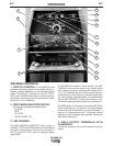
B-6
OPERATION
B-6
ARC GOUGING
The Ranger 250 can be used for limited arc gouging.
For optimal performance, set the MODE switch to CC-
STICK and the ARC CONTROL to +10.
Set the CONTROL knob to adjust output current to the
desired level for the gouging electrode being used
according to the ratings in the following table.
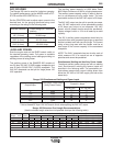
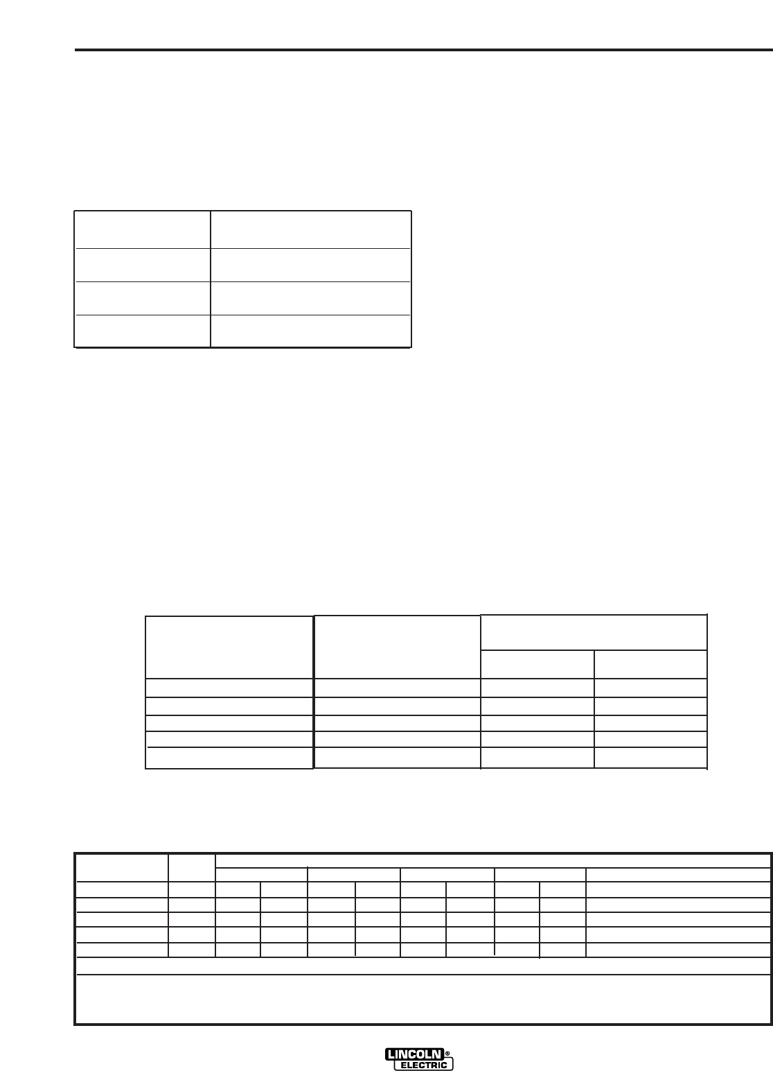
Electrode Diameter
Current Range (DC, electrode
positive)
1/8" (3.2mm) 30-60 Amps
5/32" (4.0mm) 90-150 Amps
3/16" (4.0mm) 150-200 Amps
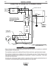
AUXILIARY POWER:
Start the engine and set the IDLER control switch to
the desired operating mode. Full power is available
regardless of the welding control settings providing no
welding current is being drawn.
The auxiliary power of the RANGER 250 consists of
two 20 Amp-120 VAC (5-20R) duplex receptacles and
one 50 Amp 120/240 VAC (14-50R) receptacle. The
240 VAC receptacle can be split for single phase 120
VAC operation.
The auxiliary power capacity is 9,000 Watts Peak,
8500 Watts Continuous of 60 Hz, single phase power.
The auxiliary power capacity rating in watts is equiva-
lent to volt-amperes at unity power factor. The max
permissible current of the 240 VAC output is 35 Amps.
The 240 VAC output can be split to provide two sepa-
rate 120 VAC outputs with a max permissible current
of 35 Amps per output to two separate 120 VAC
branch circuits (these circuits cannot be paralleled).
Output voltage is within ± 10% at all loads up to rated
capacity.
The 120 V auxiliary power receptacles should only be
used with three wire grounded type plugs or approved
double insulated tools with two wire plugs. The current
rating of any plug used with the system must be at
least equal to the current capacity of the associated
receptacle.
NOTE: The 240 V receptacle has two circuits, each of
which measure 120 V to neutral but are of opposite
polarities and cannot be paralleled.
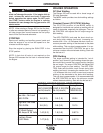
Simultaneous Welding and Auxiliary Power Loads
The above auxiliary power ratings are with no welding
load. Simultaneous welding and power loads are
specified in the following table. The permissible cur-
rents shown assume that current is being drawn from
either the 120 VAC or 240 VAC supply (not both at the
same time).
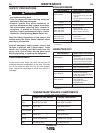
RANGER 250
Welding
Output-Amps
0
100
150
200
250
Permissible Power-Watts
(Unity Power Factor)
8500
6200
4800
3400
2000
Permissible
Current in
@120 VAC *
70**
52**
40**
28
16
Auxiliary
-Amps
@ 240 VAC
35
26
20
14
8
* Each duplex receptacle is limited to 20 amps.
** Not to exceed 35 A per 120 VAC branch circuit when splitting the 240 VAC output.
Ranger 250 Simultaneous Welding and Power Loads
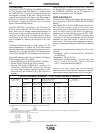
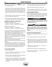
Ranger 250 Extension Cord Length Recommendations
(Use the shortest length extension cord possible sized per the following table.)
Current
(Amps)
15
20
15
20
35
Voltage
Volts
120
120
240
240
240
Load
(Watts)
1800
2400
3600
4800
8500
30
60
(9)
(18)
40
30
75
60
(12)
(9)
(23)
(18)
75
50
150
100
60
(23)
(15)
(46)
(30)
(18)
125
88
225
175
100
(38)
(27)
(69)
(53)
(30)
175
138
350
275
175
(53)
(42)
(107)
(84)
(53)
300
225
600
450
250
(91)
(69)
(183)
(137)
(76)
Maximum Allowable Cord Length in ft. (m) for Conductor Size
Conductor size is based on maximum 2.0% voltage drop.
14 AWG 12 AWG 10 AWG 8 AWG 6 AWG 4 AWG