


B-5
OPERATION
B-5
TIG WELDING
The TOUCH START TIG setting of the MODE switch is for
DC TIG (Tungsten Inert Gas) welding. To initiate a weld,
the CONTROL dial is first set to the desired current and
the tungsten is touched to the work. During the time the
tungsten is touching the work there is very little voltage or
current and, in general, no tungsten contamination. Then,
the tungsten is gently lifted off the work in a rocking
motion, which establishes the arc.
The ARC CONTROL is not active in the TIG mode. To
STOP a weld, simply pull the TIG torch away from the
work. When the arc voltage reaches approximately 30
Volts the arc will go out and the machine will reset the cur-
rent to the Touch Start level. To reinitiate the arc, retouch
the tungsten to the work and lift. Alternatively, the weld
can be stopped by releasing the Amptrol or arc start
switch.
The Ranger 250 can be used in a wide variety of DC TIG
welding applications. In general the ‘Touch Start’ feature
allows contamination free starting without the use of a Hi-
frequency unit. If desired, the K930-2 TIG Module can be
used with the Ranger 250. The settings are for reference.
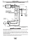
Ranger 250 settings when using the K930-2 TIG Module
with an Amptrol or Arc Start Switch:
• Set the MODE Switch to the TOUCH START TIG setting.
• Set the "IDLER" Switch to the "AUTO" position.
• Set the "WELDING TERMINALS" switch to the
"REMOTELY CONTROLLED" position. This will keep
the "Solid State" contactor open and provide a "cold"
electrode until the Amptrol or Arc Start Switch is
pressed.
When using the TIG Module, the OUTPUT control on
the Ranger 250 is used to set the maximum range of
the CURRENT CONTROL on the TIG Module or an
Amptrol if connected to the TIG Module.
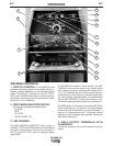
WIRE WELDING-CV
Connect a wire feeder to the Ranger 250 according to
the instructions in INSTALLATION INSTRUCTIONS
Section.
The Ranger 250 in the CV-WIRE mode, permits it to
be used with a broad range of flux cored wire
(Innershield and Outershield) electrodes and solid
wires for MIG welding (gas metal arc welding).
Welding can be finely tuned using the ARC CON-
TROL. Turning the ARC CONTROL clockwise from
–10 (soft) to +10 (crisp) changes the arc from soft and
washed-in to crisp and narrow. It acts as an induc-
tance control. The proper setting depends on the pro-
cedure and operator preference. Start with the dial set
at 0.
Listed below are some wires suitable for use on this
machine:
• Innershield - NR-311, NS-3M, NR-207, NR-203 Ni
1%, NR-204-H.
• Outershield - 0S-70, 0S-71M.
• Solid wires for MIG welding - .035 (0.9 mm), and
.045 (1.1 mm), L-50 and L-56, .035 (0.9 mm) and
.045 (1.1 mm) Blue Max MIG 308 LS.
Contact your local authorized Lincoln Electric
Distributor or the Lincoln Electric Company for specific
wires used on certain applications with this machine.
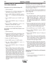
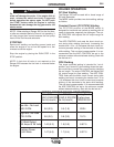
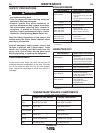
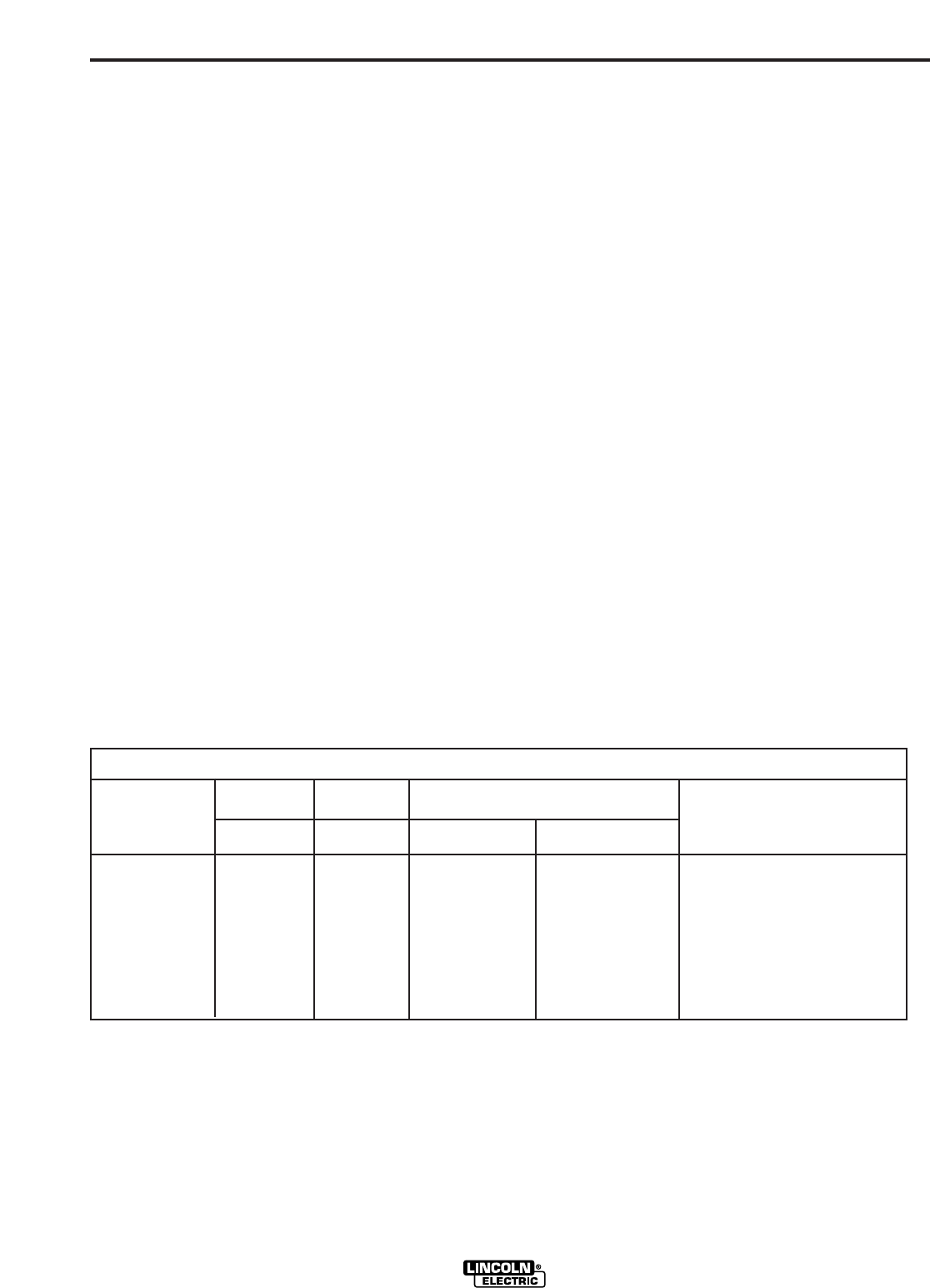
RANGER 250
TYPICAL CURRENT RANGES
(1)
FOR TUNGSTEN ELECTRODES
(2)
Tungsten Electrode DCEN (-) DCEP (+) Approximate Argon Gas Flow TIG TORCH
Diameter in. (mm) Flow Rate C.F.H. ( l /min.) Nozzle Size (4), (5)
1%, 2% Thoriated 1%, 2% Thoriated Aluminum Stainless Steel
Tungsten Tungsten
.010 (.25) 2-15 (3) 3-8 (2-4) 3-8 (2-4) #4, #5, #6
0.020 (.50) 5-20 (3) 5-10 (3-5) 5-10 (3-5)
0.040 (1.0) 15-80 (3) 5-10 (3-5) 5-10 (3-5)
1/16 (1.6) 70-150 10-20 5-10 (3-5) 9-13 (4-6) #5, #6
3/32 (2.4) 150-250 15-30 13-17 (6-8) 11-15 (5-7) #6, #7, #8
1/8 (3.2) 250-400 25-40 15-23 (7-11) 11-15 (5-7)
5/32 (4.0) 400-500 40-55 21-25 (10-12) 13-17 (6-8) #8, #10
3/16 (4.8) 500-750 55-80 23-27 (11-13) 18-22 (8-10)
1/4 (6.4) 750-1000 80-125 28-32 (13-15) 23-27 (11-13)
(1) When used with argon gas. The current ranges shown must be reduced when using argon/helium or pure helium shielding gases.
(2) Tungsten electrodes are classified as follows by the American Welding Society (AWS):
Pure EWP
1% Thoriated EWTh-1
2% Thoriated EWTh-2
Though not yet recognized by the AWS, Ceriated Tungsten is now widely accepted as a substitute for 2% Thoriated Tungsten in AC and DC applications.
(3) DCEP is not commonly used in these sizes.
(4) TIG torch nozzle "sizes" are in multiples of 1/16ths of an inch:
# 4 = 1/4 in. (6 mm)
# 5 = 5/16 in. (8 mm)
# 6 = 3/8 in. (10 mm)
# 7 = 7/16 in. (11 mm)
# 8 = _ in. (12.5 mm)
#10 = 5/8 in. (16 mm)
(5) TIG torch nozzles are typically made from alumina ceramic. Special applications may require lava nozzles, which are less prone to breakage, but cannot withstand high temperatures
and high duty cycles.