


A-5
INSTALLATION
RANGER 305G
A-5
MUFFLER OUTLET PIPE
Using the clamp provided secure the outlet pipe to the
outlet tube with the pipe positioned such that it will
direct the exhaust in the desired direction. Tighten
using a 9/16" socket or wrench.
SPARK ARRESTER
Some federal, state or local laws may require that
gasoline or diesel engines be equipped with exhaust
spark arresters when they are operated in certain
locations where unarrested sparks may present a fire
hazard. The standard muffler included with this welder
does not qualify as a spark arrester. When required by
local regulations, a suitable spark arrester, such as
the K1898-1 must be installed and properly main-
tained.
An incorrect spark arrestor may lead to damage to
the engine or adversely affect performance.
------------------------------------------------------------------------
HIGH FREQUENCY GENERATORS FOR
TIG APPLICATIONS
The K930-2 TIG Module is suitable for use with the
RANGER 305G. The RANGER 305G and any high
frequency generating equipment must be properly
grounded. See the K930-2 Operating Manual for com-
pleted instructions on installation, operation, and
maintenance.
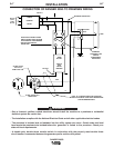
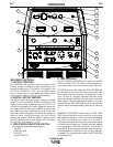
REMOTE CONTROL
The RANGER 305G is equipped with a 6-pin and a
14-pin connector. The 6-pin connector is for connect-
ing the K857 or K857-1 Remote Control (optional) or
for TIG welding, the K870 foot Amptrol or the K963-3
hand Amptrol.
When in the CC-STICK, PIPE, and CV-WIRE modes
and when a remote control is connected to the
Amphenol, the auto-sensing circuit in the RANGER
305G automatically switches the OUTPUT control
from control at the welder to remote control.
The 14-pin connector is used to directly connect a
wire feeder or TIG Module (K930-2) control cable. In
the CV-WIRE mode, the RANGER 305G auto-sensing
circuit automatically makes the RANGER 305G
Output Control inactive and the wire feeder voltage
control active when the control cable is connected to
the 14-pin connector.
NOTE: When a wire feeder with a built in welding volt-
age control is connected to the 14-pin connector, do
not connect anything to the 6-pin connector.
ELECTRICAL CONNECTIONS
MACHINE GROUNDING
Because this portable engine driven welder creates its
own power, it is not necessary to connect its frame to
an earth ground, unless the machine is connected to
premises wiring (home, shop, etc.)
To prevent dangerous electric shock, other equipment
to which this engine driven welder supplies power
must:
• Be grounded to the frame of the welder using a
grounded type plug.
• Be double insulated. Do not ground the machine
to a pipe that carries explosive or combustible
material.
------------------------------------------------------------------------
When this welder is mounted on a truck or trailer, its
frame must be electrically connected to the metal
frame of the vehicle, use a #8 or larger copper wire
connected between the machine grounding stud and
frame of the vehicle. When this engine driven welder
is connected to premises wiring such as that in a
home or shop, its frame must be connected to the
system earth ground. See further connection instruc-
tions in the section entitled "Standby Power
Connections" as well as the article on grounding in the
latest U.S. National Electrical Code and the local
code.
In general, if the machine is to be grounded, it should
be connected with a #8 or larger copper wire to a solid
earth ground such as a metal water pipe going into
the ground for at least ten feet and having no insulat-
ed joints, or to the metal framework of a building
which has been effectively grounded.
The U.S. National Electrical Code lists a number of
alternate means of grounding electrical equipment. A
machine grounding stud marked with the symbol
is provided on the front of the welder.
WELDING TERMINALS
The RANGER 305G is equipped with a toggle switch
for selecting "hot" welding terminal when in the
"WELD TERMINALS ON" position or "cold" welding
terminal when in the "REMOTELY CONTROLLED"
position.
WARNING
CAUTION