


B-3
OPERATION
B-3
CV-WIRE mode: In this mode, turning the ARC CONTROL
clockwise from –10 (soft) to +10 (crisp) changes the arc from
soft and washed-in to crisp and narrow. It acts as an induc-
tance control. The proper setting depends on the procedure
and operator preference. Start with a setting at 0.
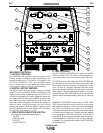
5. WELD OUTPUT TERMINALS WITH FLANGE
NUT:
Provides a connection point for the electrode and work
cables.
6. GROUND STUD:
Provides a connection point for connecting the machine case
to earth ground for the safest grounding procedure.
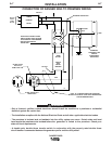
7. 14 PIN CONNECTOR:
For attaching wire feeder control cables to the RANGER
305G. Includes contactor closure circuit , auto-sensing
remote control circuit, and 120V and 42V power. The remote
control circuit operates the same as the 6 Pin Amphenol.
8. 6 PIN CONNECTOR:
For attaching optional remote control equipment. When in
the CC-STICK, PIPE, and CV-WIRE modes and when a
remote control is connected to the Amphenol, the auto-sens-
ing circuit in the RANGER 305G automatically switches the
OUTPUT control from control at the welder to remote control.
When using the TOUCH START TIG
®
mode with a TIG
Module connected to the RANGER 305G, the OUTPUT con-
trol on the front of the RANGER 305G is used to set the
maximum current range of the CURRENT CONTROL on the
TIG Module.
9. WELD TERMINALS CONTROL SWITCH:
In the WELD TERMINALS ON position, the output is electri-
cally hot all the time. In the REMOTELY CONTROLLED
position, the output is controlled by a wire feeder or amptrol
device, and is electrically off until a remote switch is
depressed.
10. WIRE FEEDER VOLTMETER SWITCH:
Matches the polarity of the wire feeder voltmeter to the polar-
ity of the electrode.
ENGINE CONTROLS:
11. RUN/STOP SWITCH - RUN position energizes the
engine prior to starting. STOP position stops the engine. The
oil pressure interlock switch prevents battery drain if the
switch is left in the RUN position and the engine is not oper-
ating.
12. CHOKE - When pulled out, it closes the choke valve
on the engine carburetor for quick starting.
13. START PUSH BUTTON
- Energizes the starter motor to crank the engine
14. IDLER SWITCH
- Has two positions as follows:
1) In the HIGH position, the engine runs at the high
idle speed controlled by the engine governor.
2) In the AUTO position, the idler operates as follows:
• When switched from HIGH to AUTO or after start-
ing the engine, the engine will operate at full
speed for approximately 12 seconds and then go
to low idle speed.
• When the electrode touches the work or power is
drawn for lights or tools (approximately 100
Watts minimum), the engine accelerates and
operates at full speed.
• When welding ceases or the AC power load is
turned off, a fixed time delay of approximately 12
seconds starts. If the welding or AC power l o a d
is not restarted before the end of the time delay,
the idler reduces the engine speed to low idle
speed.
• The engine will automatically return to high idle
speed when there is welding load or AC power
load reapplied.
15. ELECTRIC FUEL GAUGE
The electric fuel gauge gives accurate and reliable
indication as to how much fuel is in the fuel tank.
16. ENGINE HOUR METER – Displays the total
time that the engine has been running. This meter is
useful for scheduling prescribed maintenance.
STARTING AND STOPPING THE ENGINE
• Remove all plugs connected to the AC power
receptacles.
• Set IDLER switch to AUTO.
• Set the RUN/STOP switch to RUN.
• Pull the choke to the full out position.
• Press and hold the engine START button until the
engine starts.
• Release the engine START button when the engine
starts.
• Push the choke back in.
• The engine will run at high idle speed for approxi-
mately 12 seconds and then go to low idle speed.
Allow the engine to warm up at low idle for several
minutes before applying a load and/or switching to
high idle. Allow a longer warm up time in cold
weather.
RANGER 305G