


D-9
TROUBLESHOOTING
D-9
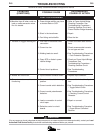
Check the resistance reading between 75 on the ter-
minal strip and 211 on SW #2. The reading must be
10K ohms. No reading will indicate an open rheostat
and a low reading will indicate a shorted or partially
shorted rheostat; in either case, replace.
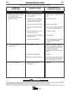
TOGGLE SWITCH CHECK
1. Turn off the machine power input. SW #1 has 115
volts across it when the input power is connected.
2. Isolate the switch to be tested by removing all con-
necting leads.
3. Check to make sure the switch is making connec-
tions with a V.O.M. meter. The meter should read
zero resistance.
4. Put the ohmmeter on X1K scale and measure the
resistance between the terminal and the case of the
machine (touch a self tapping screw). Reading
should be infinite.
5. If either step (3) or step (4) fails, replace the switch.
REMOTE CONTROL CHECK
Disconnect the remote field control and connect an
ohmmeter across 75 and 76 and rotate the rheostat in
the remote control. The resistance reading should go
from zero to 10K ohms. Repeat with ohmmeter across
77 and 76 with same results. Connect ohmmeter
across 75 and 77. The reading should be 10K ohms. A
lower reading will indicate a shorted or partially short-
ed rheostat. A very high reading will indicate an open
rheostat. In either of the last two cases, replace the
rheostat. Check for any physical damage.
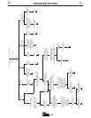
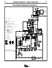
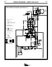
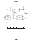
CHECKING POWER RECTIFIER BRIDGE
ASSEMBLY
Precise evaluation of diodes or SCRs require
laboratory equipment. If a bridge problem still
exists after test, please call a Lincoln Field
Service Shop.
Equipment Needed:
1. V.O.M. or ohmmeter for diodes
2. Circuit Diagram 1 for SCRs
DEVICE ISOLATION (See the instruction manual
parts list for the exact location.)
Disconnect the following leads from the bridge,
shown in Diagram 2:
1. Wiring harness gate leads (G1, G2, G3) from
gate lead connector J4 on control P.C. Board
2. AC leads X1, X2, and X3 from the anodes of the
SCRs and cathodes of the diodes.
3. The 200, 221, 222, and 223 leads from the
Snubber P.C. Board.
4. Lead 220 that connects to the latching resistor
(R3).
5. The cathode of each diode (4 total).
POWER DIODE TEST
1. Establish the polarity of the ohmmeter leads and
set to the X10 scale.
2. Connect the ohmmeter positive led to anode and
negative lead to the cathode.
3. Reverse the leads of the ohmmeter from Step 2.
4. A shorted diode will indicate zero or an equally
low resistance in both directions. An open diode
will have an infinite or high resistance in both
directions; and a good diode will have a low
resistance in Step 2 and a much higher resis-
tance in Step 3.
POWER SILICON CONTROLLED
RECTIFIER TEST
The SCR must be mounted in the heat sink when mak-
ing this test.
1. Connect the ohmmeter (set to the X10 scale) leads
to the anode and cathode.
2. Reverse the leads of the ohmmeter from Step 1.
3. A shorted SCR will indicate zero or an equally low
resistance in one or both directions.
4. Establish the polarity of the ohmmeter. Connect the
positive lead to the gate and the negative lead to
the cathode.
E500
CAUTION