


A-1
INSTALLATION
A-1
LOCATION
FALLING EQUIPMENT can cause
injury.
• Do not lift this machine using lift
bail if it is equipped with a heavy
• accessory such as trailer or gas cylinder.
• Lift only with equipment of adequate lifting
capacity.
• Be sure machine is stable when lifting.
Install the welder in a dry location where there is a free
circulation of air in through the front louvers and out the
back of the case. A location which minimizes the
amount of smoke and dirt drawn into the front louvers
reduces the chance of dirt accumulation that can block
air passages, causing overheating and nuisance shut-
down of the machine.
INPUT WIRING
ELECTRIC SHOCK can kill.
• Have an electrician install and ser-
vice this equipment.
• Turn the input power off at the fuse
box before working on equipment.
• Do not touch electrically hot parts.
Welder is rated for 230/460/575V input and is shipped
from the factory connected for 460V input. To change
the connection, see the wiring or connection diagram
pasted to the inside of the access panel in the case
back.
Be sure the voltage, phase and frequency of the input
power is as specified on the welder nameplate.
Have a qualified electrician remove the access panel in
the case back and connect the three phase AC power
to terminals L
1
, L
2
, L
3
of the input contactor in accor-
dance with the U. S. National Electrical Code, all local
codes, and the wiring diagram located inside the
machine.
The welder frame must be grounded. A stud marked
with the symbol located on the floor of the input box is
provided for this purpose. See the U.S. National
Electrical Code for details on proper grounding meth-
ods.
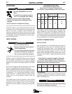
Recommended Input Wire,
Ground Wire and Fuse Sizes
Based on U.S. National Electrical Code.
For 60 hertz, 3 phase Welders at 60% Duty Cycle.
This welder is rated for 500 Amps 60% duty cycle. Duty
cycle is based on a ten minute period. Therefore, the
welder can be operated at nameplate rated output for
6 minutes of every 10 minute period without overheat-
ing. An amber high temperature warning light provides
a visual indication of an over temperature condition.
OUTPUT CONNECTIONS
OUTPUT STUDS
With the machine off, run electrode and work cables of
the appropriate sizes (see the following table) up
through the rectangular holes in the machine base
located below the output studs. Connect the cable lugs
to the output terminals marked (+) and (-) or, if the
welder comes equipped with the polarity switch option
“electrode” and “to work”. Tighten the holding nuts with
a wrench.
Cable Sizes for Combined Length of Electrode
and Work Cable (Copper) at 60% Duty Cycle
Extreme care must be observed when installing or
extending the wiring of a remote control.
TIG WELDING
The E500 is shipped with proper R.F. By-pass circuitry
installed to protect the control circuit when TIG welding
with a TIG Module unit.
To provide protection, the welder frame grounding
stud must be connected to ground.
------------------------------------------------------------------------
E500
WARNING
WARNING
Copper Wire Size
Type 75°C in Conduit
Input Amps 3 Input 1 Ground Super Lag Fuse
Welder Volts Input Wires Wire Size in Amps
E500 230 100 4 6 150
460 50 8 8 70
575 40 10 10 60
CAUTION
Machine Up to 100 ft. 100 to 150 ft. 150 to 200 ft. 200 to 250 ft.
Size (30 m) (30 – 46 m) (46 – 61 m) (61 – 76 m)
E500 2/0 (68 mm
2
) 3/0 (86 mm
2
) 3/0 (86 mm
2
) 4/0 (108 mm
2
)