


B-1
OPERATION
B-1
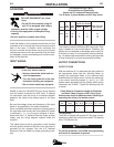
ELECTRIC SHOCK can kill.
• Do not touch electrically live parts
or electrode with skin or wet cloth-
ing.
• Insulate yourself from work and ground.
• Always wear dry insulating gloves.
FUMES AND GASES can be danger-
ous.
• Keep your head out of fumes.
• Use ventilation or exhaust to
• remove fumes from breathing zone.
WELDING SPARKS can cause fire or
explosion.
• Keep flammable material away.
• Do not weld on containers that
have held combustibles.
ARC RAYS can burn.
• Wear eye, ear and body protection.
NOTE: The P.C. Board is protected by a moisture
resistant coating. When the welder is operated, this
coating will “bake off” of certain power resistors that
normally operate at high temperatures, emitting some
smoke and odor for a short time. These resistors and
the P.C. Board beneath them may become blackened.
This is a normal occurrence and does not damage the
component or affect the machine performance.
NOTE: The cooling fan on this unit is controlled by a
thermostat to operate only when it is needed.
1. To Start the Welder, move the “Power” switch to
“On”. This starts the welder and lights the white pilot
light on the machine control panel. This light indi-
cates that the line contactor is energized).
2. Setting Welding Current
a. The “Current Control” dials on the front of the
machine indicates the output current at the
NEMA arc voltage. The “A” range controls the
current over about 1/2 of the range of the “B”
range. A toggle switch on the control panel
allows selection of the desired range. The output
control can be adjusted while welding.
b. Provisions for remote control are standard. A
current control switch on the machine control
panel labeled “Current Control at E500” or
“Current Control Remote” is provided for select-
ing the desired mode of operation, either at the
machine or remote, Be certain the machine
remote switch is in the machine position, unless
a remote control is connected.
c. The “Arc Force Control”, located on the right side
of the front control panel, is calibrated from one
to ten. Lower settings will provide less short cir-
cuit current and a softer arc. A setting that is too
low may cause the electrode to stick in the pud-
dle. Higher settings will provide a higher short
circuit current, a more forceful arc, and possibly
more spatter. For most welding, the dial should
be set at approximately mid range (5 – 6).
Adjustment up or down can then be made
depending on the electrode, procedures, and
operator preference. For most TIG welding appli-
cations adjust this control to minimum for best
operating characteristics.
115 VAC Duplex Receptacle (Code 10649 only)
The duplex receptacle is located near the output
studs and is protected by a 15 amp circuit breaker.
115 VAC GFCI Receptacle (Codes 11042 and above)
The GFCI receptacle is located near the output studs
and is protected by a 15 amp circuit breaker.
OPTIONAL EQUIPMENT
1. Undercarriage – (K817, K817R) includes a spring
loaded handle for hand towing and a choice of
wheels.
2. Remote Control - Supplied by Red-D-Arc.
E500
WARNING