


A-6
INSTALLATION
BIG RED™ 600
A-6
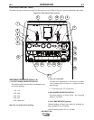
AUXILIARY POWER RECEPTACLES
The auxiliary power of the BIG RED™ 600 consists of
Single Phase 60Hz Power. Out put Voltage is within
+/- 10% at loads up to rated capacity.
One 120VAC NEMA (5-20R) 20 amp duplex recepta-
cle is protected by a 20 amp circuit breaker that pro-
vides 2400 watts Peak / 2400 watts Continuous
power. Maximum current is 20 amps total.
One 120VAC European (IEC-309) 16 amp receptacle
is protected by a 15 amp circuit breaker that provides
1800 watts Peak / 1800 watts Continuous power.
Maximum current is 15 amps.
One 240VAC European (IEC-309) 16 amp receptacle
is protected by a 15 amp 2-pole circuit breaker that
provides 3600 watts Peak / 3600 watts Continuous
power. The 2-pole circuit breaker disconnects both hot
leads at the same time. Maximum current is 15 amps.
120 V RECEPTACLES
A GFCI module protects, the two 120V Auxiliary
Power receptacles. A GFCI (Ground Fault Circuit
Interrupter) electrical receptacle is a device to protect
against electric shock should a piece of defective
equipment connected to it develop a ground fault. If
this situation should occur, the GFCI module will trip,
removing voltage from the output of the receptacle. If
a GFCI module is tripped see the MAINTENANCE
section for detailed information on testing and reset-
ting it. A GFCI module should be properly tested at
least once every month.
The 120 V auxiliary power receptacles should only be
used with three wire grounded type plugs or approved
double insulated tools with two wire plugs. The current
rating of any plug used with the system must be at
least equal to the current capacity of the associated
receptacle.
RESIDUAL CURRENT DEVICE READY
The BIG RED™ 600 is configured to allow for the
addition of a Residual Current Device (RCD) to pro-
tect the 240V Single Phase Receptacle. The auxiliary
power area on the front panel of the BIG RED™ 600
has a hole sized and shaped to accept a typical 2-pole
(RCD) along with a protective rubber boot. A cover
plate with a label “RCD READY” covers the hole and
secures a mounting bracket on the backside of the
panel.
Note: The (RCD) should be rated for at least 15 amps.
There are many suppliers of RCD’s. One example is
Allen Bradley, part number 1492-RCD2A40.
The protective boot can be obtained from:
APM-Hexseal, part number HE-1035
See Section F Diagrams of this Operator’s Manual for
instructions on installing an RCD and protective rub-
ber boot.
STANDBY POWER CONNECTIONS
The BIG RED™ 600 is suitable for temporary, standby
or emergency power using the engine manufacturer’s
recommended maintenance schedule.
The BIG RED™ 600 can be permanently installed as
a standby power unit for 240 VAC(60Hz). Connections
must be made by a licensed electrician who can
determine how the 120/240 VAC power can be adapt-
ed to the particular installation and comply with all
applicable electrical codes.
Take necessary steps to assure load is limited to the
capacity of the BIG RED™ 600
• Only a licensed, certified, trained electrician
should install the machine to a premises or resi-
dential electrical system. Be certain that:
• The installation complies with the National
Electrical Code and all other applicable electrical
codes.
• The premises is isolated and no feedback into
the utility system can occur. Certain state and
local laws require the premises to be isolated
before the generator is linked to the premises.
Check your state and local requirements.
------------------------------------------------------------------------
WARNING