


B-2
OPERATION
B-2
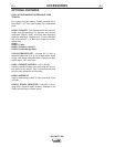
WELDING CONTROLS (Items 1-5)
1. OUTPUT RANGE SELECTOR SWITCH
A 5 position switch that provides 5 overlapping out-
put current settings:
• 65 - 115
• 105 - 220
• 150 - 330
• 200 - 435
• 300 – Maximum
Note: Do not switch while welding
2. OUTPUT CONTROL
Provides fine adjustment of the current and open
circuit voltage from minimum to maximum within
each Range.
“1’’ is minimum and “10” is maximum.
3. WELD MODE SELECTOR SWITCH
Provides selection of either Stick / Arc Gouging
Mode or TIG Mode.
4. VOLT/AMP METERS (optional)
Optional analog volt and amp meter kit available for
easy installation into front panel.
(See Accessory Section For “K” number)
BIG RED™ 600
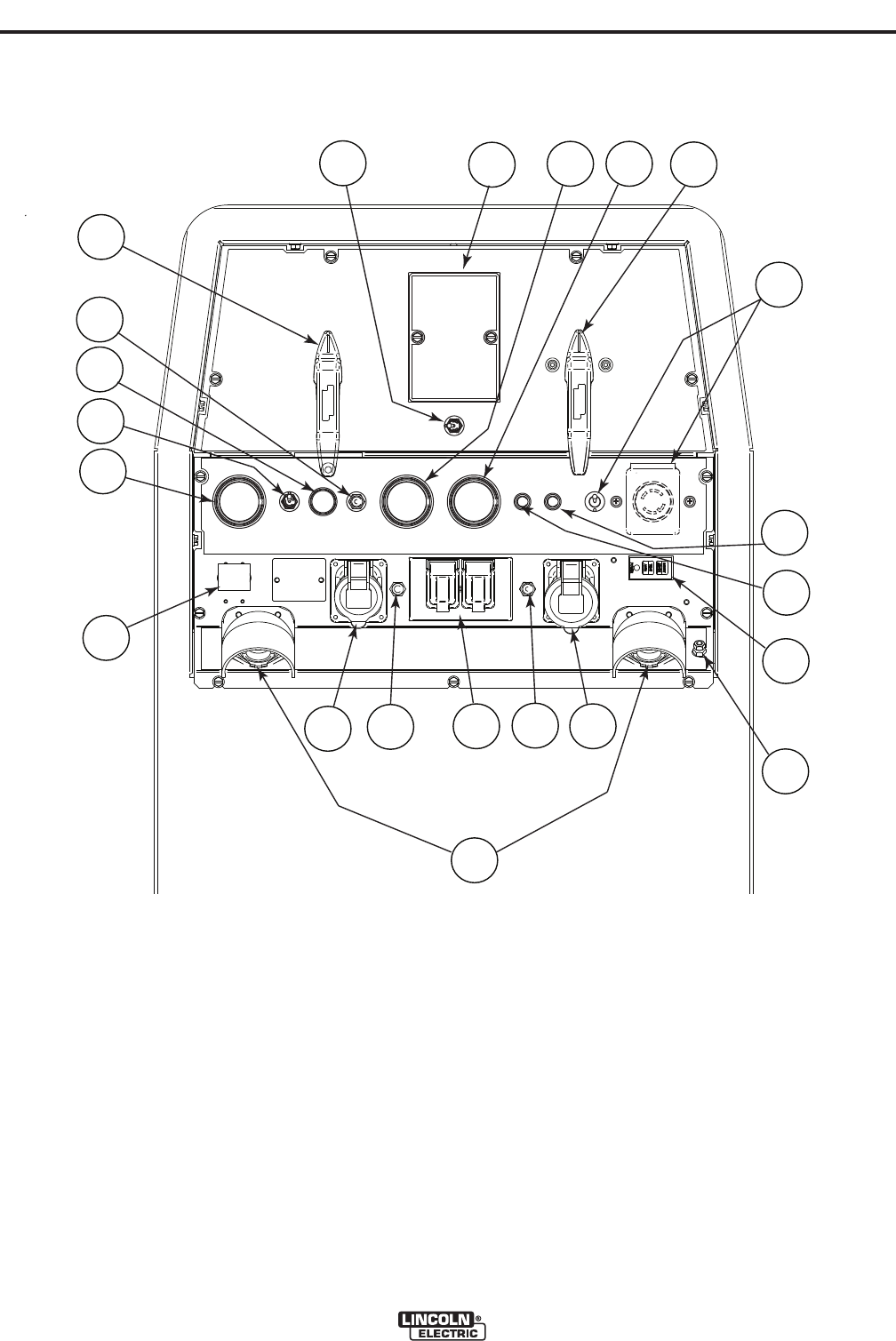
CONTROLS AND SETTINGS
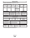
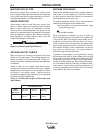
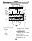
All welder and engine controls are located on the case front panel. Refer to Figure B.1 and the explanations that follow.
Figure B.1 Case Front Panel Controls
3
1
9
4
8
7
11
12
2
14
13
21
5
6
10
15
16
17
18
19
20
22