


!&+,$$,!'&
$&R(!(
+ !$!&+'&&,!'&
0$!&*?3K 7JB>A67 ;8
63?3976
Q #77B5K>;@67DGBD;9:F3@6
5:3;@76FAEGBBADF
Q#77B5K>;@67D3I3K8DA?3D73EI:7D7;F?3K47
63?3976
Q&7H7D>;8FI7>67DI;F:5K>;@67D3FF35:76
Q&7H7D3>>AII7>6;@97>75FDA67FAFAG5:5K>;@67D
Q#77B5K>;@67D3I3K8DA?I7>6;@9ADAF:7D>;H7
7>75FD;53>5;D5G;FE
Q-!$-( '+ !$!&+ %0
*% $, '*#!$$
Q+:GF A88 E:;7>6;@993E EGBB>K I:7@@AF
;@GE7
Q+77?7D;53@ &3F;A@3> +F3@63D6 1+387FK
;@ /7>6;@9 3@6 GFF;@9W (G4>;E:76 4K F:7
?7D;53@/7>6;@9+A5;7FK
------------------------------------------------------------------------
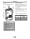
Maximum inlet pressure is 100 psi. (6.9 bar.)
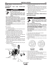
Install the shielding gas supply as follows:
1. Secure the cylinder to prevent it from falling.
2. Remove the cylinder cap. Inspect the cylinder valves
and regulator for damaged threads, dirt, dust, oil or
grease. Remove dust and dirt with a clean cloth. '
&', ,, , *-$,'*!'!$ *+
'*%!+(*+&,Inform your gas supplier
of this condition. Oil or grease in the presence of high
pressure oxygen is explosive.
3. Stand to one side away from the outlet and open the
cylinder valve for an instant. This blows away any dust
or dirt which may have accumulated in the valve out-
let.
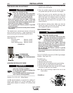
4. Attach the flow regulator to the cylinder valve and
tighten the union nut(s) securely with a wrench. Note:
if connecting to 100% CO
2
cylinder, insert regulator
adapter between regulator and cylinder valve. If
adapter is equipped with a plastic washer, be sure it is
seated for connection to the CO
2
cylinder.
5. Attach one end of the inlet hose to the outlet fitting of
the flow regulator. Attach the other end to the welding
system shielding gas inlet. Tighten the union nuts with
a wrench.
6. Before opening the cylinder valve, turn the regulator
adjusting knob counterclockwise until the adjusting
spring pressure is released.
7. Standing to one side, open the cylinder valve slowly a
fraction of a turn. When the cylinder pressure gage
stops moving, open the valve fully.
8. The flow regulator is adjustable. Adjust it to the flow
rate recommended for the procedure and process
being used before making a weld.
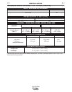
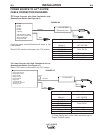
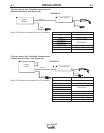
/*&!&
(;@
A
B
C
D
E
/;D;@9
5 volt supply
Not used
Trigger
83% WFS switch
5 volt supply
$'&&,!'&+
There is one circular connector for the gun trigger on
the front of the LN™-25 PIPE.
G@5F;A@
5-pin trigger
connector for
push-guns
only.
A
E
C
B
D
A
E
C
B
D