


THUMB
SCREW
GUN
!&+,$$,!'&
$&R(!(
(*++-**%"-+,%&,
$,*!+ '#53@=;>>
Q,GD@F:7;@BGFBAI7D'3FF:7I7>6
;@9BAI7DEAGD57478AD7;@EF3>>3F;A@AD
5:3@9;@96D;H7DA>>E3@6AD9G;67E
QA@AFFAG5:7>75FD;53>>K>;H7B3DFE
Q/:7@;@5:;@9I;F: F:79G@FD;997D 7>75FDA67
3@6 6D;H7 ?75:3@;E?3D7:AF FAIAD= 3@6
9DAG@63@65AG>6D7?3;@7@7D9;L76E7H7D3>E75
A@6E38F7DF:79G@FD;997D;ED7>73E76
QA@AFAB7D3F7I;F: 5AH7DEB3@7>EAD9G3D6E
D7?AH76ADAB7@
Q'@>KCG3>;8;76B7DEA@@7>E:AG>6B7D8AD??3;@F7
@3@57IAD=
------------------------------------------------------------------------
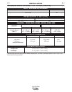
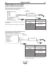
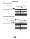
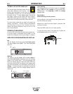
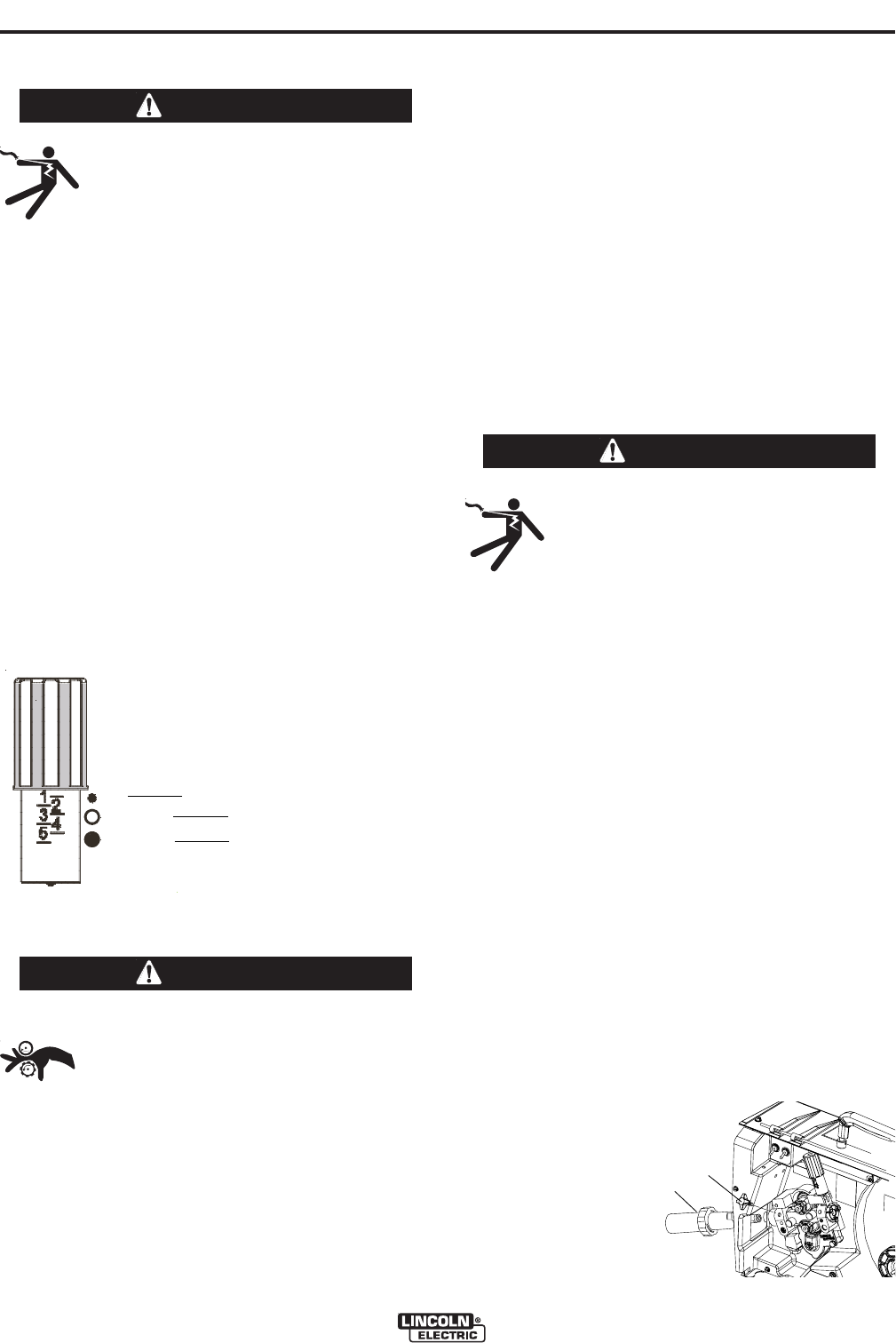
The pressure arm controls the amount of force the
drive rolls exert on the wire. Proper adjustment of the
pressure arm gives the best welding performance.
Set the pressure arm as follows:
(See Figure A.3)
Aluminum wires between 1 and 2
Cored wires between 2 and 3
Steel, Stainless wires between 3 and 5
$'!&+(''$+'/!*
Q#77B:3@6E:3;D5>AF:;@93@6FAA>E
3I3K8DA?DAF3F;@97CG;B?7@F
QA@AFI73D9>AH7EI:7@F:D736;@9I;D7
AD5:3@9;@9I;D7EBAA>
Q'@>KCG3>;8;76B7DEA@@7>E:AG>6;@EF3>>
GE7ADE7DH;57F:;E7CG;B?7@F
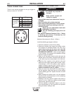
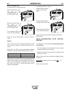
Loading 10 to 15 lb. (4.5 – 6.8kg) Spools.
A K468 spindle adapter is required for loading 2"
(51mm) wide spools on 2" (51mm) spindles. Use a
K468 spindle adapter for loading 2-1/2" (64mm) wide
spools.
1. Squeeze the release bar on the retaining collar and
remove it from the spindle.
2. Place the spindle adapter on the spindle, aligning
the spindle brake pin with the hole in the adapter.
3. Place the spool on the spindle and align the
adapter brake tab with one of the holes in the back
side of the spool. An indicator mark on the end of
the spindle shows the orientation of the brake tab.
Be certain the wire feeds off of the spool in the
proper direction.
4. Re-install the retaining collar. Make sure that the
release bar snaps out and that the retaining collar
fully engages the groove on the spindle.
-&'&&,!'&
$,*!+ '#53@=;>>
Q,GD@F:7;@BGFBAI7D'3FF:7I7>6
;@9BAI7DEAGD57478AD7;@EF3>>3F;A@AD
5:3@9;@96D;H7DA>>E3@6AD9G;67E
QA@AFFAG5:7>75FD;53>>K>;H7B3DFE
Q/:7@;@5:;@9I;F: F:79G@FD;997D 7>75FDA67
3@6 6D;H7 ?75:3@;E?3D7:AF FAIAD= 3@6
9DAG@63@65AG>6D7?3;@7@7D9;L76E7H7D3>E75
A@6E38F7DF:79G@FD;997D;ED7>73E76
QA@AFAB7D3F7I;F: 5AH7DEB3@7>EAD9G3D6E
D7?AH76ADAB7@
Q'@>KCG3>;8;76B7DEA@@7>E:AG>6B7D8AD??3;@F7
@3@57IAD=
------------------------------------------------------------------------
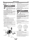
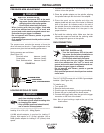
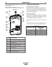
The LN™-25 PIPE comes with a K1500-2 gun adapter
installed. (See Figure A.4)
To install a gun,
1. Turn power OFF.
2. Remove the thumb screw.
3. Push the gun the completely into the gun bushing.
4. Secure the gun in place with the thumb screw.
5. Connect the trigger cable from the gun to the trigger
connector on the front of the feeder.
Note: Not all gun bushings require the use of the
thumb screw.
/*&!&
/*&!&
6
Al
Fe, CrNi
Fe, CrNi
ALUMINUM WIRES
CORED WIRES
STEEL, STAINLESS WIRES
!-*
/*&!&
!-*