


,*'-$+ '',!&
$&R(!(
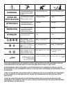
Observe all Safety Guidelines detailed throughout this manual
If for any reason you do not understand the test procedures or are unable to perform the tests/repairs safely, contact your
$A53>$;@5A>@GF:AD;L76;7>6+7DH;5735;>;FK for technical troubleshooting assistance before you proceed.
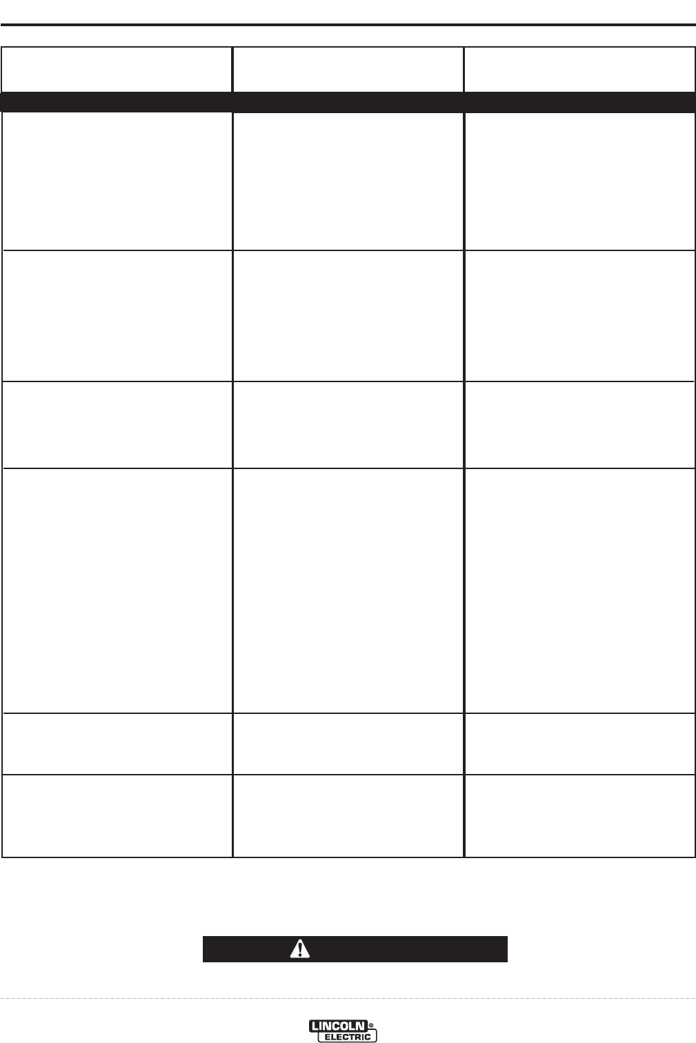
-,!'&
(*'$%+
+0%(,'%+
('++!$
-+
*'%%&
'-*+',!'&
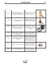
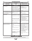
Wire feed speed consistently oper-
ates at the wrong value. The speed
changes when the wire feed speed
knob is adjusted.
The wire feed speed stuck at 200-
300 in/min and there is no change
when the wire feed speed knob is
adjusted.
Variable or "hunting" arc.
When the trigger is pulled, the wire
feeds slowly.
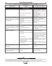
Poor arc starts with sticking or
"blast-offs", weld porosity, narrow
and ropy looking bead.
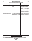
7. Incorrect tension arm pressure on
the drive rolls.
8. The spindle brake is too tight.
9. Worn drive roll.
1. The jumper lead for normal
speed/extra torque is connected
improperly.
2. The wrong gear is installed in the
wire drive.
3. The brushes on the motor are
worn.
1. The tachometer is connected
improperly.
2. The tachometer has failed.
1. Wrong size, worn and/or melted
contact tip.
2. Worn work cable or poor work
connection.
3. Wrong polarity.
4. The gas nozzle is extended
beyond the contact tip or the wire
stickout is too long.
5. Poor gas shielding on processes
requiring gas.
The Run-In switch is “ON”
1. Improper procedures or tech-
niques.
7. Adjust the tension arm per the
Instruction Manual. Most elec-
trodes feed well at a tension arm
setting of "3".
8. Verify the spool of wire moves
with minimal effort.
9. Replace the drive rolls if worn or
filled with dirt.
1. Properly connect the normal
speed/extra torque jumper.
2. Install the proper pinion gear in
the wire drive.
3. Replace the motor/gearbox
assembly.
1. Verify all of the tachometer leads
are properly connected.
2. Replace the motor and tachome-
ter assembly.
1. Replace the contact tip.
2. Verify all work and electrode con-
nections are tight and that the
cables are in good condition.
Clean/replace as necessary.
3. Adjust polarity to the recommend-
ed procedure.
4. Adjust the gas nozzle and shorten
the stickout to 3/8 to 1/2 inches.
5. Check gas flow and mixture.
Remove or block sources of
drafts.
Use the set-up Push-button to turn
Run-in OFF.
1. See "Gas Metal Arc Welding
Guide" (GS-100).
'GFBGF(DA4>7?E