


!&+,$$,!'&
$&R(!(
/!**!.'&!-*,!'&
(See Figure A.2)
&!& , -& *!.*
-+ !&
$,*!+ '#53@=;>>
Q,GD@F:7 ;@BGF BAI7D '3FF:7
I7>6;@9 BAI7D EAGD57 478AD7 ;@EF3>
>3F;A@AD5:3@9;@96D;H7DA>>E 3@6AD
9G;67E
QA@AFFAG5:7>75FD;53>>K>;H7B3DFE
Q/:7@;@5:;@9I;F: F:79G@FD;997D 7>75FDA67
3@6 6D;H7 ?75:3@;E?3D7:AF FAIAD= 3@6
9DAG@63@65AG>6D7?3;@7@7D9;L76E7H7D3>E75
A@6E38F7DF:79G@FD;997D;ED7>73E76
QA@AFAB7D3F7I;F: 5AH7DEB3@7>EAD9G3D6E
D7?AH76ADAB7@
Q'@>KCG3>;8;76B7DEA@@7>E:AG>6B7D8AD??3;@F7
@3@57IAD=
------------------------------------------------------------------------
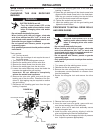
Tools required:
• 1/4" hex key wrench.
Note: Some gun bushings do not require the use of
the thumb screw.
1. Turn power off at the welding power source.
2. Remove the welding wire from the wire drive.
3. Remove the thumb screw from the wire drive.
4. Remove the welding gun from the wire drive.
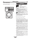
5. Loosen the socket head cap screw that holds the
connector bar against the gun bushing.
!?BADF3@F A @AF 3FF7?BF FA 5A?B>7F7>K
D7?AH7F:7EA5=7F:73653BE5D7I
6. Remove the outer wire guide, and push the gun
bushing out of the wire drive. Because of the pre-
cision fit, light tapping may be required to remove
the gun bushing.
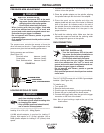
7. Disconnect the shielding gas hose from the gun
bushing, if required.
8. Connect the shielding gas hose to the new gun
bushing, if required.
9. Rotate the gun bushing until the thumb screw hole
aligns with the thumb screw hole in the feed plate.
Slide the gun receiver bushing into the wire drive
and verify the thumb screw holes are aligned.
10. Tighten the socket head cap screw.
11. Insert the welding gun into the gun bushing and
tighten the thumb screw.
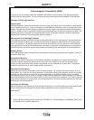
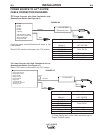
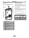
GUN RECEIVER BUSHING
LOOSEN TIGHTEN
THUMB SCREW
OUTER WIRE GUIDE
SOCKET HEAD
CAP SCREW
CONNECTOR BLOCK
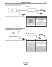
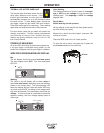
GUN RECEIVER BUSHING
LOOSEN TIGHTEN
THUMB SCREW
OUTER WIRE GUIDE
SOCKET HEAD
CAP SCREW
CONNECTOR BLOCK
/*&!&
(*'-* ,' !&+,$$ *!. *'$$+
&/!*-!+
Q ,GD@F:7;@BGF BAI7D'3FF:7
I7>6;@9BAI7DEAGD57 478AD7;@EF3>
>3F;A@AD 5:3@9;@96D;H7DA>>E 3@6AD
9G;67E
QA@AFFAG5:7>75FD;53>>K>;H7B3DFE
Q/:7@;@5:;@9I;F: F:79G@FD;997D 7>75FDA67
3@6 6D;H7 ?75:3@;E?3D7:AF FAIAD= 3@6
9DAG@63@65AG>6D7?3;@7@7D9;L76E7H7D3>E75
A@6E38F7DF:79G@FD;997D;ED7>73E76
QA@AFAB7D3F7I;F: 5AH7DEB3@7>EAD9G3D6E
D7?AH76ADAB7@
Q'@>KCG3>;8;76B7DEA@@7>E:AG>6B7D8AD??3;@F7
@3@57IAD=
------------------------------------------------------------------------
1. Turn power off at the welding power source.
2. Release the idle roll pressure arm.
3. Remove the outer wire guide by turning the knurled
thumbscrews counter-clockwise to unscrew them
from the feed plate.
4. Rotate the triangular lock and remove the drive
rolls.
5. Remove the inner wire guide.
6. Insert the new inner wire guide, groove side out,
over the two locating pins in the feed plate.
7. Install a drive roll on each hub assembly secure
with the triangular lock.
8. Install the outer wire guide by aligning it with the
pins and tightening the knurled thumbscrews.
9. Close the idle arm and engage the idle roll pressure
arm. Adjust the pressure appropriately.
/*&!&
!-*