


OPERATING INSTRUCTIONS
NL Option Kit
(Not Required With NA-3, NA-5, LT-7 or LT-56)
The K783 NL option kit (for field installation) is designed
to permit use of the NA-2, LAF-3, LT-3 and the LT-3 section
of the LT-34 tractor with DC-1500’s assigned code 7687
and above. It provides the necessary DC control power for
the operation of the equipment and the necessary circuitry
for proper inching, cold starting and arc striking. In using
the NL option kit a K775 remote field control is required and
is included as part of the option kit. (See pg 6, paragraph e.)
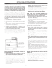
The NL option kit consists of a sheet metal box, 12.5” long,
11.5” deep and 5.7” high. This box mounts on top of the
DC-1500 and the following controls are located on the front
of the box:
1. Inch speed control — used for LT tractor only.
2. Hot start control — used to obtain optimum arc strik-
ing.
3. Polarity switch — changes polarity of control circuit to
correspond with electrode polarity.
4. Contactor dropout delay switch — switches in or out
a slight contactor dropout delay to prevent sticking of
the wire in the crater at the end of welding.
The terminal strip for connection to the automatic equip-
ment is located under the front cover. All necessary control
leads for connection to the DC-1500 are wired into the NL
kit for easy connection to the DC-1500 terminal strip.
Before proceeding with any installation, be certain the
DC-1500 is turned off.
1. Mount the NL option box to the top of the DC-1500
with the screws used to fasten the roof and sides.
2. Remove the cover of the NL option for access to the
terminal strip.
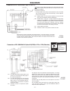
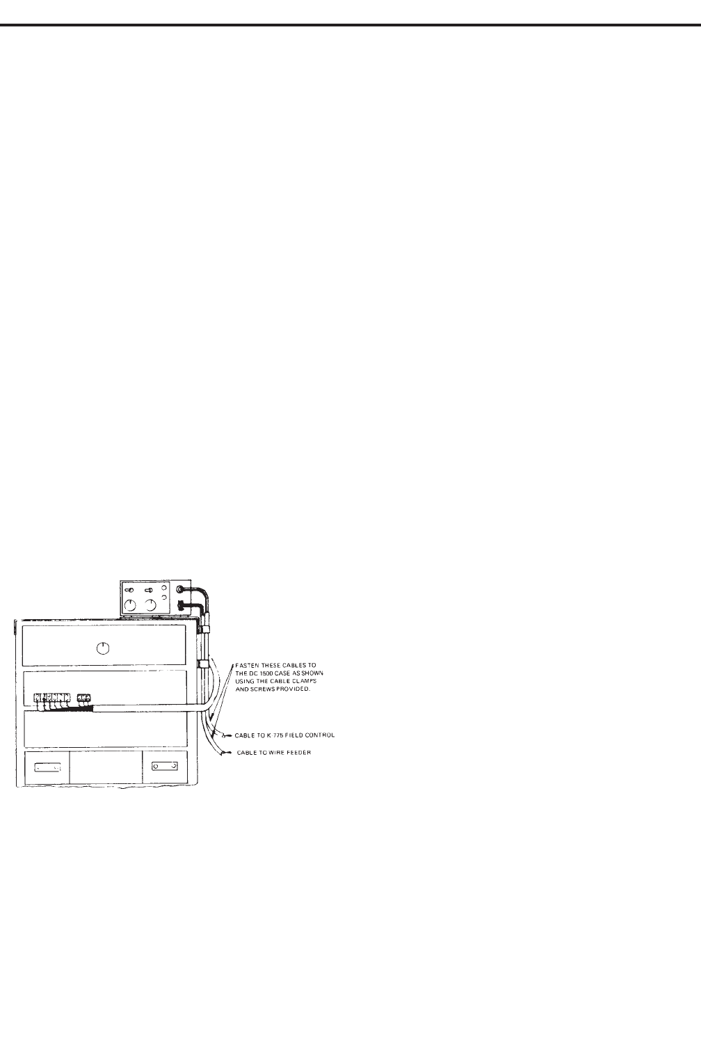
3. Feed the control cable from the automatic wire feed
control unit through the grommet on the front of the
NL box. Connect the control leads per the appropriate
connection diagram included at the back of this man-
ual. Secure the cables to the case with the clamps and
screws provided.
4. Using the same diagram, connect the leads from the
option kit to the DC-1500 terminal strip.
5. Feed the K775 control cable through the clamp on the
front of the NL option box and connect the leads to
terminals 75,76, and 77 per connection diagram.
6. Replace the cover. This completes the installation.
NOTE: An NL Option was factory installed inside
DC-1500’s built to codes 7562-NL, 7636-NL and 7676-NL.
The instructions for the K783 apply except as follows:
1. The factory-installed NL Option does not have a sep-
arate “POS — NEG” switch.
2. The factory-installed NL Option does not have an “Inch
Speed” control.
3. It cannot be used with LT-3 or LT-34 wire feeders.
4. The fuse protecting the 115 volt DC circuit is a 2 amp
fuse located on the NL Option panel inside the welder.
Operation When Connected to the NA-2
1. Set the “POS — NEG” switch (on both NL Option &
DC-1500) to correspond to the polarity of the electrode
cable connection.
2. Set the mode switch on the front of the DC-15000 to
“Constant Voltage — Innershield” or “Constant Volt-
age — Sumerged Arc”.
3. Set the toggle switch on the front of the DC-1500 to
“Output Control Remote”.
4. Set the output as required for the procedures using the
K775 Remote Output Control shipped with the NL Op-
tion.
5. Set the NA-2 inch speed to a speed lower than welding
feed speed for good starting using the control on the
NA-2. The NL Option “Inch Speed” control is not in
the circuit.
6. Set the “Hot Start Control” on the NL Option to 4.
7. Set the “Contactor Drop-Out Delay” switch to “Off”.
Refer to the NA-2 Operating Manual for instructions
for setting the contactor drop-out delay and crater fill-
ing features built into the NA-2 circuit.
Operation When Connected to the LAF-3 and the K783
NL Option Kit
For proper arc striking and welding when using the LAF-3
with the DC-1500 and K783 NL Option Kit, follow the
instructions below (Turn the input power off at the fuse box
before working inside the machine.):
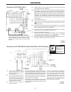
1. Connect the DC-1500 NL option, and LAF-3 per the
connection diagram M13321.
2. Remove the cover from the LAF-3 control box.
-10-