


-5-
LOCATION
Install the welder in a dry location where there is free cir-
culation of air in through the louvers in the front and out
through the louvers in the back of the case. A location which
minimizes the amount of smoke and dirt drawn into the
machine reduces the chance of dirt accumulation that can
block air passages and cause overheating.
INPUT WIRING
Failure to fuse the input lines per the specifications in this
manual will constitute customer abuse and void the war-
ranty.
---------------------------------------------------------------------
Be sure the voltage, phase and frequency of the input power
is as specified on the welder nameplate.
Have a qualified electrician remove the lower right side case
panel and connect 3 phase AC power to terminals L
1
, L
2
and L
3
of the input contactor in accordance with the Na-
tional Electrical Code, all local codes and the wiring diagram
located inside the machine.
The frame of the welder must be grounded. A stud marked
with the symbol located on the fan shroud is provided
for this purpose. See the U.S. National Electrical Code for
details on proper grounding methods.
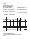
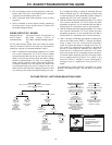
Recommended Input Wire, Grounding Wire and Fuse Sizes
Based on National Electrical Code For 60 Hertz,
INSTALLATION
3 Phase Welders at 100% Duty Cycle
NOTE: The standard machines are designed to operate on
460 volt-60 Hertz, 440 volt-50 Hertz and 380 volt-50 Hertz
input power systems. However, to use the machines on 380
volt-50 Hertz power, reconnect the transformer input leads
in accordance with the connection diagram pasted to the
inside of the lower right side case panel.
OUTPUT CONNECTION (Turn Power Source
Off)
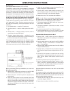
a. Output Studs
The “Positive” and “Negative” output studs are located
on the front panel. Two of each are provided to simplify
connecting multiple electrode or work cables as sug-
gested in the table below.
Connect the electrode cables to the “Positive” studs for
electrode positive (DC+) polarity or to the “Negative”
stud for electrode negative (DC-) polarity as required
by the welding procedures. Connect the work cables to
the other set of studs. Tighten the nuts with a wrench.
b. Auxiliary Power
This machine supplies the 1000 volt-amperes of 115
volt, AC power needed for the automatic wire feeders.
The power is available from terminals #31 and #32 on
the terminal strip.
c. “NL Option” (K783)
Installation of an NL option is required when connect-
ing a DC-1500 to LAF-3, NA-2, LT-3 or LT-34 wire
feeding systems. See the section on page 9 entitled “NL
Option Kit” for full information.
d. Wire Feeder Connection — Without NL Option
Turn the welder off. Remove the screw and lift the
hinged door on the front of the control panel to expose
the terminal strips. Connect the leads of the wire feeder
input control cable to the terminal strip exactly as spec-
ified in the appropriate connection diagram included in
the wire feeder Operating Manual. Attach the control
cable to the panel at the right of the terminal strip using
the clamp attached to the control cable. Close the door
and replace the screw.
To connect the DC-1500 to wire feeders not covered in
available connection diagrams, write to the factory for
instructions giving complete nameplate information for
the DC-1500 and wire feeder.
Copper Wire Size
Type 75° In Conduit
Input Amps 3 Input Grounding Super Lag Fuse
Volts Input Wires Conductor Size in Amps
460 184 000 3 300
Suggested Copper Cable Sizes — 80% Duty Cycle
Below 1000 amps Two 4/0
1000 to 1200 amps Three 4/0
Up to
1200 to 1500 amps Four 4/0
200’
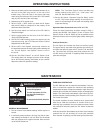
WARNING
FALLING
EQUIPMENT can
cause injury.
• Do not lift this machine using lift
bale if it is equipped with a
heavy accessory such as a trailer
or gas cylinder.
• Lift only with equipment of
adequate lifting capacity.
• Be sure machine is stable when
lifting.
WARNING
ELECTRIC SHOCK
can kill.
• Have an electrician install and
service this equipment.
• Turn the input power off at the
fuse box before working on
equipment.
• Do not touch electrically hot
parts.