


P.C. BOARD TROUBLESHOOTING GUIDE
3. LED L3 indicates power is being applied to fault pro-
tection relay 2CR, when wire feeder button is pressed
or jumper is connected across 2 and 4.
4. LED L4 indicates when fault protection circuit is being
activated.
5. LED L5 indicates a control signal is being supplied to
the firing circuit. As the output control is varied, LED
L5 should change brilliancy.
FIRING CIRCUIT P.C. BOARD
Machine settings Terminals #2 and #4 jumpered on
for P.C. board DC-1500. Output Control at
troubleshooting
DC-1500. Variable Voltage opera-
tion.
All nine light emitting diodes must be lit when the power
source is turned on and the wire feed arc start button is
pressed or a jumper is connected between 2 and 4.
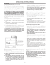
1. LED L7 indicates AC power being supplied to P.C. board
from control transformer T2. If not lit, check voltage
across terminals 203 and 204 on the terminal strip lo-
cated on the left side of the bottom fan baffle. Voltage
should be approximately 115 volts. If no voltage indi-
cates a supply problem, check wiring and transformer.
If voltage is present, turn the machine off, remove the
12-pin harness plug from the P.C. board, turn the ma-
chine back on and check the voltage across pins 2 and
3 on the plug. This should be approximately 115 volts.
If no voltage and there is voltage at terminals 203 and
204 on terminal strip TS-1 this indicates a broken lead
or loose terminal on either lead 203 or 204.If voltage is
present and LED L7 is not lit, replace P.C. board.
2. LED L8 indicates AC power being supplied to P.C. board
from control transformer T3. If not, follow the same
procedure as above in (1) for terminals 205 and 206 on
terminal strip TS-1 and pins 5 and 6 on the connector.
3. LED L9 indicates AC power being supplied to P.C. board
from control transformer T4. If not, follow the same
procedure as above in (1) for terminals 207 and 208 on
terminal strip TS-1 and pins 9 and 12 on the connector.
4. LED L1 through L6 indicate gate signals are being sup-
plied to the main power SCR’s L1 through L6 respec-
tively. If light L5 on the “Control/Fault Protection”
circuit P.C. board and lights L7 through L9 on the “Fir-
ing” circuit P.C. board are lit and LED’s L1 through L6
are not lit, check lead 231 between the “Firing” P.C.
board and the “Control/Fault Protection” P.C. board
that is not broken and is connected to each connector.
If the lead shows continuity and LED L1 through L6 are
not lit, replace the”Firing Circuit” P.C. board. If any
one of the LED’s L1 through L6 is not lit and lights L7
through L9 are lit, replace the “Firing Circuit” P.C.
board.
If troubleshooting guide indicates a possible P.C. board
problem, the guide on page ? can be used to locate the
problem.
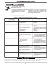
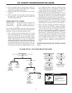
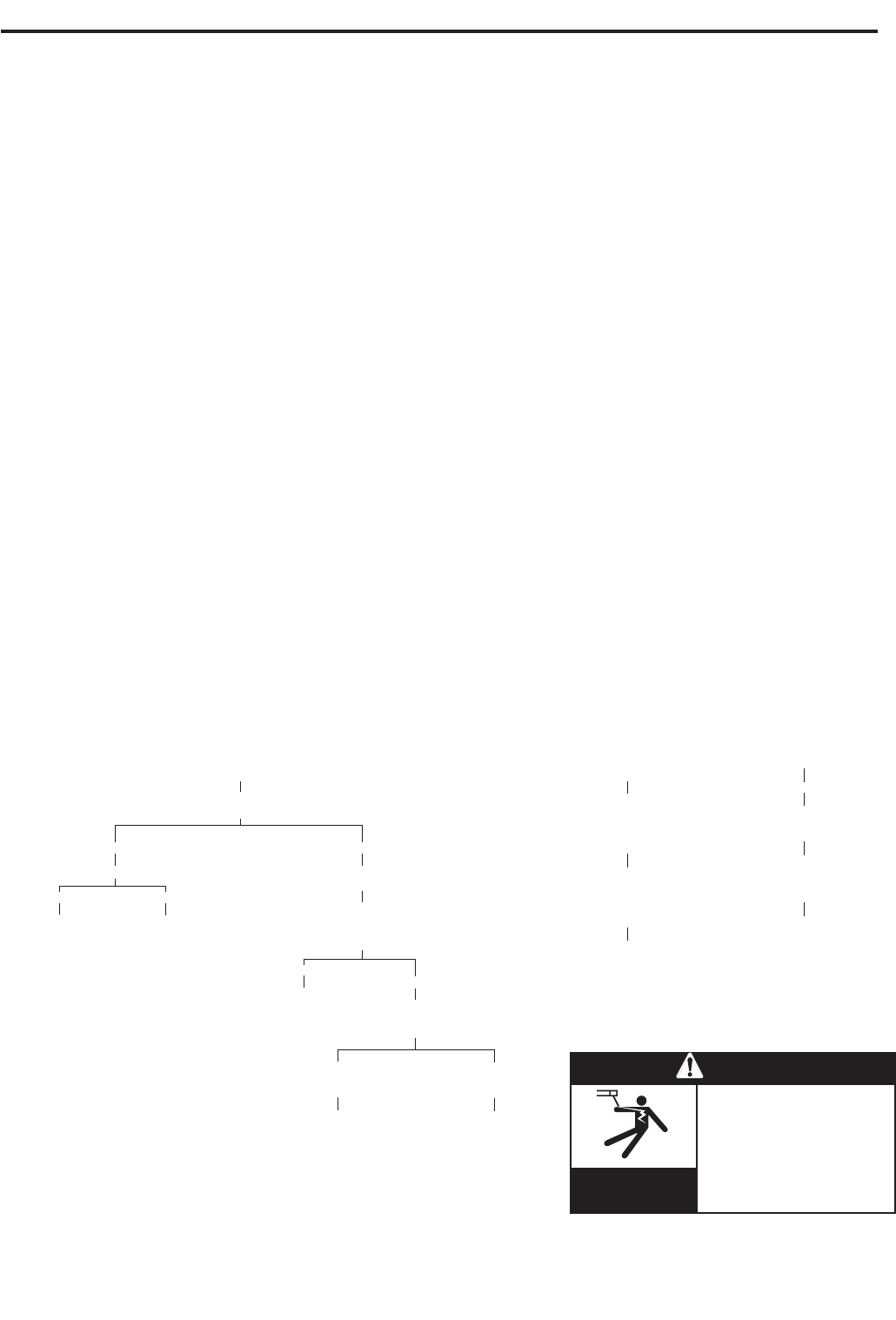
OUTLINE FOR DC-1500 TROUBLESHOOTING GUIDE
NO WELDER OUTPUT MACHINE HAS OUTPUT BUT ERRATIC WELDING
(INPUT CONTACTOR “ON” TERMINALS 2 AND 4 CLOSED) TRIPS OFF IMMEDIATELY
CHECK PROCEDURE
CHECK CONTROL BOARD CHECK FOR SHORT
LED L5 BETWEEN ELECTRODE AND CHECK MODE SWITCH FOR
WORK LEADS, REMOVE PROPER POSITION FOR
EXTERNAL LEADS FROM PROCESS BEING USED
IF OFF IF ON THE OUTPUT TERMINALS
CHECK LED’S
CHECK LED L1 CHECK “FIRING” BOARD IF TROUBLE STILL L4, L5, L6
LED’S PERSISTS, FOR EQUAL
IF OFF IF ON CHECK LED L3 ON BRILLIANCY
ALL “CONTROL/FAULT
CHECK AC REPLACE NINE LIGHTS PROTECTION” BOARD IF LIGHTS ARE NOT ALL
INPUT TO “CONTROL/ SHOULD APPROXIMATELY EQUAL
“CONTROL/ FAULT BE ON IF LIGHT GOES ON,THEN BRIGHT, REPLACE
FAULT PROTECTION” QUICKLY OUT WHEN START FIRING P.C. BOARD
PROTECTION” BOARD IF YES BUTTON IS PRESSED,
BOARD IF NO “CONTROL/FAULT
POSSIBLE CHECK GATE PROTECTION” BOARD IS
DEFECTIVE T7 LEAD CHECK DEFECTIVE AND SHOULD
TRANSFORMER CONNECTIONS LED’S BE REPLACED
TO SCR’S L7, L8, L9
IF ONE IF ON AND
OR MORE OTHER LIGHTS
ARE OUT ARE OUT
CHECK AC REPLACE
INPUT TO FIRING
BOARD, BOARD
203-204, 205-206
207-208
POSSIBLE
DEFECTIVE
TRANSFORMERS
T2, T3, OR T4
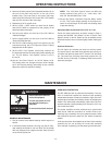
• Have an electrician install and
service this equipment.
• Turn the input power off at the
fuse box before working on
equipment.
• Do not touch electrically hot parts.
ELECTRIC SHOCK
can kill.
WARNING
-14-