


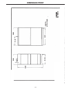


DIAGRAMS
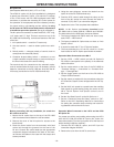
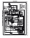
Connection of DC-1500 to NA-3 (All), LT-5 or LT-7
Above diagram shows electrode connected positive. To change polarity, turn power
source off, reverse the electrode and work leads at the power source and position the switch
on power source to proper polarity. Also reverse the leads on the back of the ammeter and
voltmeter in the automatic control box.
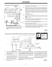
Connect the control cable ground lead to the frame terminal marked
near the power source terminal strip. The power source must
be properly grounded.
To automatic control box.
* If using an older control cable: Connect lead #75 to #75 on terminal
strip, connect lead #76 to #76 on terminal strip, connect lead #77
to #77 on terminal strip.
N.A. Welding cables must be of proper capacity for the current and
duty cycle of immediate and future applications.
N.B. Extend lead 21 using #14 or larger insulated wire physically
suitable for the installation. An S16586 remote voltage sensing
work lead is available for this purpose. Connect it directly to
the work piece keeping it separate from the welding
work lead circuit and connection for convenience, this extended
#21 lead should be taped to the welding work lead.
N.C. Tape up bolted connection.
N.D. Terminals 73 and 74 not present on earlier DC-1500.
S15534
2-26-82B
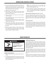
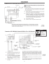
Connection of DC-1500 With NL Option Kit (K783) to LT-3 or LT-34 (Obsolete)
N.A. On codes above 8234 extend lead 67 and
connect it to the electrode cable going to
the automatic equipment.
N.B. On codes below 8234 this is #67 and the
LT-3 or LT-34 #67 lead can be connected
either to #67 or to the electrode cable ter-
minal as shown. Terminal 82 not present
on later DC-1500’s.
N.C. Terminals 73 and 74 not present on earlier
DC-1500’s.
This diagram shows the electrode connected positive. To change
polarity, turn power source off, reverse the electrode and work
leads at the power source and position the switch on the power
source and th NL option kit to the proper polarity. Also reverse
the leads on the back of the ammeter and voltmeter in the LT-3
control box.
Contactor drop out delay switch on the NL option kit must be in
the “On” position.
The 4/0 cables shown will handle up to 1000 amps at 80% duty
cycle. For higher currents or duty cycle add additional cables to
the power source output studs.
M13322
2-26-82C
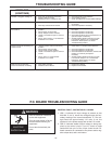
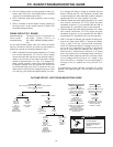
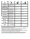
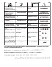
•Do not operate with covers
removed.
•Disconnect welding power source
before servicing.
•Do not touch electrically live
parts.
•Only qualified persons should
install, use or service this
machine.
ELECTRIC SHOCK
can kill.
WARNING
-17-