


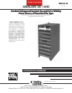
OPERATING INSTRUCTIONS
To Set for Machine or Remote Control
The output can be controlled either at the wire feeder or
the DC-1500. When the NL Option Kit is installed, how-
ever, output is controlled only from the K775 Remote Con-
trol usually mounted at the wire feeder.
To adjust the output from the wire feeder, set the toggle
switch on the front of the DC-1500 to “Output Control
Remote”. To adjust the output using the DC-1500 “Output
Control” rheostat, set this switch to “Output Control at DC-
1500”.
To Set the Welder Output
With the toggle switch set to “Output Control at DC-1500”,
rotating the “Output Control” rheostat on the DC-1500
from 1 to 10 increases the machine output from minimum
to maximum. The same full range control is set from the
wire feeder or K775 when the toggle switch is set to “Output
Control Remote”.
Set the output as required by the welding procedures.
Mode Switch
The toggle switch labeled CV Innershield, CV submerged
arc, VV submerged arc, is used to select the proper welder
characteristics for the process being used.
NOTE: Some machines say ”VV” for variable voltage while
other machines use the terminology “CC” for constant cur-
rent.
The CV Innershield Mode permits the DC-1500 to produce
essentially a flat output characteristic that can be varied
from approximately 20 to 60 volts. In this position the dy-
namic characteristics of the machine under welding con-
ditions provides optimum welding characteristics for
Innershield welding and other open arc processes.
The CV Submerged Arc Mode also produces an essentially
flat output characteristics that can be varied from approxi-
mately 20 to 60 volts. The dynamic characteristics of the
CV Submerged Arc Mode are such that excellent submerged
arc welding can be obtained for most procedures that pre-
viously required a constant current type power source.
The VV Submerged Arc Mode permits the DC-1500 to pro-
duce a constant current output characteristic through the
range of 200A-28V to 1500A-60V with an open circuit volt-
age of 45 to 98 volts. Although almost all submerged arc
welding can now be done in the CV mode, the VV mode
is available for those procedures where VV (CC) may still
be desirable.
Set-up for Various Processes
Selection of mode switch position — There are several gen-
eral rules to follow in the selection of the mode switch posi-
tion.
1. Use the CV Innershield mode for all Innershield weld-
ing.
2. Use the CV Submerged Arc mode for most submerged
arc welding. However, some high speed welding pro-
cedures may perform better on the CV Innershield
mode.
3. The VV (CC) mode is available for high current, large
puddle submerged arc procedures that cannot be done
as well with the constant voltage mode.
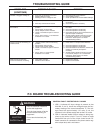
4. Air Carbon Arc Gouging or Cutting — For air carbon
arc gouging, the constant voltage Innershield mode is
used with the output control set between 4 and max.
depending on the application, carbon size, etc. Up to
1
/
2
” carbons, start with the machine control set at 4 and
increase as required for long cable lengths. With
1
/
2
”
and
5
/
8
” carbons, short (100’) cable lengths can lead to
occasional tripout of the protection circuit when the
carbon is shorted to the work. Cutting back the output
setting will reduce the short circuit current and mini-
mize tripping. Longer cable lengths do an even better
job since this also reduces the short circuit current but
even more significantly permits raising the open circuit
voltage (by increasing control setting) for smoother op-
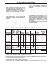
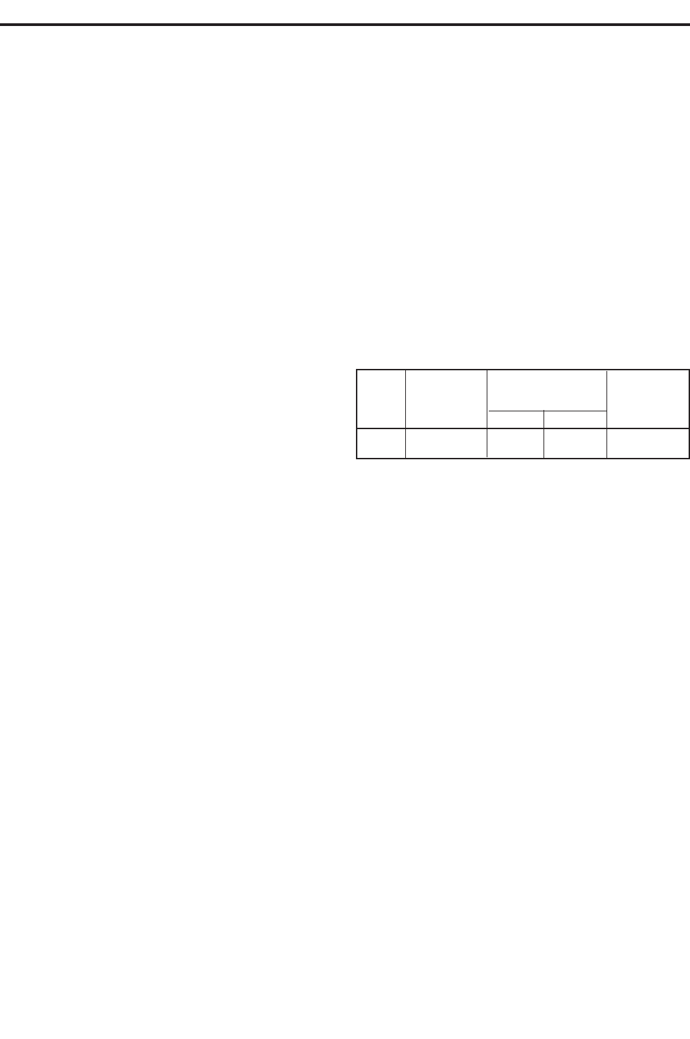
eration. See the table below for optimum cable size and
length.
If ever longer leads are used and the output control is
already set on max., the unit has reached its maximum
air carbon arc capability.
3
/
4
” carbons are not recommended for use with the
DC-1500 because the high surge currents that occur
with this diameter can cause the DC-1500 fault pro-
tection circuitry to trip the machine off the line, if the
operator does not gouge in such a way to limit the cur-
rents.
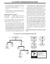
General Set-Up Procedures When Using DC-1500 and
Lincoln Automatic Head NA-3
(Read the following and refer also to the chart on page 9.)
1. NA-3 — The NA-3 should be set for the mode being
used on the power source. If using either of the CV
modes, the NA-3 VV board switch should be set for
CV. If the power source is used in the VV mode, then
the NA-3 VV board mode switch should be placed in
the VV position.
All NA-3’s when used with the DC-1500 are capable of
cold starting with the variable voltage board mode
switch in VV. Cold starting permits the wire to be
inches down to the work, automatically stop and au-
tomatically energize the flux hopper valve. All NA-3’s
made after September 1976, are capable of cold starting
on either CV or VV settings of the variable voltage board
switch.
Combined Total
Electrode and
Electrode
Carbon Typical
Work Lead Length
and Work
Size Current Range (Min) (Max) Lead Size
1
/
2
600-1000 Amps 250’ 825’ 2 — 4/0
5
/
8
800-1200 Amps 375’ 925’ 3 — 4/0
-7-