


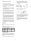

LN-9 GMA Connection Instructions
1. Turn the Invertec power switch “off”.
2. Connect the K596 control cable assembly from the
LN-9 GMA to the Invertec control cable connector.
The control cable connector is located at the rear
of the Invertec.
3. Connect the electrode cable to the output terminal
of polarity required by electrode. Connect the work
lead to the other terminal.
4. Place the local-remote switch in the “remote” posi-
tion to allow output control at the LN-9 GMA.
5. Set the meter polarity switch on the rear of the
Invertec to coincide with wire feeder polarity used.
The wire feeder will now display the welding volt-
age.
6. K608-1 adapter is required in LN-9 GMA for LN-9
type control. K608-1 is installed in line with P10
connection at the LN-9 GMA voltage board. See
diagram S20607 at the back of this manual.
7. K442-1 Pulse Power Filter Board is also required
for GMAW, but should be disconnected for FCAW.
8. If K596 is not available, see connection diagram
S20608 at the back of this manual for modification
of K196 LN-9 GMA input cable with K867 universal
adapter plug.
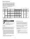
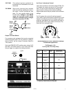
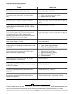
Output Cables
Select the output cable size based upon the following
chart.
Cable sizes for Combined Length of Electrode and
Work Cable (Copper) 75° rated:
Duty Length Up 61-76m
Cycle Current 61m (200 ft.) (200-250 ft.)
100% 250 1/0 1/0
60% 300 1/0 2/0
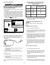
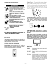
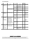
Quick Disconnect Plugs
A quick disconnect system is used for the welding
cable connections. The welding plug included with the
machine is designed to accept a welding cable size of
1/0 to 2/0.
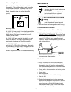
1. Remote 25mm (1 in.) of welding cable insulation.
– 10 –
2. Slide rubber boot onto cable end. The boot end
may be trimmed to match the cable diameter.
Soap or other lubricant will help to slide the boot
over the cable.
3. Slide the copper tube into the brass plug.
4. Insert cable into copper tube.
5. Tighten set screw to collapse copper tube. Screw
must apply pressure against welding cable. The
top of the set screw will be well below the surface
of the brass plug after tightening.
6. Slide rubber boot over brass plug. The rubber
boot must be positioned to completely cover all
electrical surfaces after the plug is locked into the
receptacle.
25 mm
1 in.
WELDING CABLE
BOOT
TRIM
SET SCREW
BRASS PLUG
COPPER TUBE