


–– 8 –
INPUT VOLTAGE SETUP
POWER CORD CONNECTION
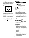
A 10 ft. (3.0m) power cord is provided and wired into
the machine. Follow the power cord connection
instructions. Incorrect connection may result in equip-
ment damage.
Single Phase Input
1. Connect green lead to ground per U.S. National
Electrical Code.
2. Connect black and white leads to power.
3. Wrap red lead with tape to provide 600V insula-
tion.
Three Phase Input
1. Connect green lead to ground per U.S. National
Electrical Code.
2. Connect black, red and white leads to power.
Install in accordance with all local and national electric
codes.
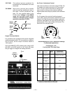
CONNECTION OF WIRE FEEDERS TO THE
INVERTEC
(Note: IEC units do not have 110 VAC auxiliary
power).
LN-25 Connection Instructions
1. Turn the Invertec power switch “off”.
2. Connect the electrode cable to the output terminal
of polarity required by electrode. Connect the work
lead to the other terminal.
3. LN-25 with remote control options K431 and K432.
Use K876 adapter with K432 cable or modify K432
cable with K867 universal adapter plug. See con-
nection diagram S19899 and S19309 or S19405 at
the back of this manual.
4. Place the local-remote switch in the “remote” posi-
tion if output control is desired at the wire feeder
rather than the Invertec. (LN-25 must have K431
and K432 options for remote output control opera-
tion).
LN-7 Connection Instructions
1. Turn the Invertec power switch “off”.
2. Connect the K480 control cable from the LN-7 to
the Invertec control cable connector. The control
cable connector is located at the rear of the
Invertec.
3. Connect the electrode cable to the output terminal
of polarity required by electrode. Connect the work
lead to the other terminal.
4. Place the local-remote switch in the “local” posi-
tion to allow output control at the Invertec. (K864
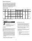
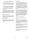
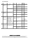
Recommended Fuse Sizes Based On The U.S.
National Electrical Code And Maximum
Machine Outputs
Fuse Size in Amps
Input Volts
(1)
(Time Delay Fuses)
3 phase 208 60
50/60 Hz 230 60
460 40
1 phase 208
(2)
85
50/60 Hz 230
(2)
80
460 50
3 phase 575 30
60 Hz
(1)
Input voltage must be within ±10% of rated value.
(2)
When operating on these inputs, at outputs exceeding 200A/60%
or 165A/100%, the input line cord should be changed to an input
conductor of 6 AWG or larger.
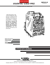
THE LINCOLN ELECTRIC CO. CLEVELAND, OHIO U.S.A.
.
.
.
.
Do not touch electrically live parts.
Only qualified persons should install,
use or service this equipment.
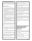
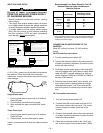
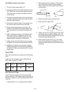
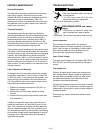
RECONNECT PROCEDURE
REPLACE WITH A 3 AMP SLOW BLOW ONLY.
1. BE SURE POWER SWITCH IS OFF.
200-208V
220-230V
380-415V
440-460V
’A’
INPUT VOLTAGE RANGE.
removed.
Do not operate with wraparound
inspecting or servicing machine.
Disconnect input power before
IF MACHINE CEASES TO OPERATE (NO METER, NO FAN)
2. CONNECT LEAD ’A’ TO DESIRED
3. POSITION SWITCH TO DESIRED INPUT VOLTAGE RANGE.
S20324
AND THERE IS NO OTHER KNOWN FAILURE: CHECK FUSE;
VOLTAGE=380-460V
VOLTAGE=200-230V
9-11-92
BLACK
GREEN
RED
WHITE
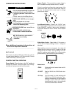
DO NOT ATTEMPT TO POWER THIS UNIT
FROM THE AUXILIARY POWER SUPPLY
OF AN ENGINE WELDER.
• Special protection circuits may operate, causing
loss of output.
• The supply from engine welders often has exces-
sive voltage peaks because the voltage waveform
is usually triangular shaped instead of sinusoidal.
• If voltage peaks from the engine welder exceed
380V, the input circuits of this machine protecting
the filter capacitors, FETS and other components
from damage will not
be energized .
---------------------------------------------------------------------
CAUTION